Automobile grille machining mold

A technology for processing molds and grilles, applied in the field of automobile grille processing molds, can solve the problems of low degree of automation, poor cooling effect, slow cooling speed, etc., and achieve the effect of high degree of automation, fast workpiece forming, and fast cooling speed.

Inactive Publication Date: 2017-02-22
JIANGSU YUYAN MOLD IND
View PDF0 Cites 8 Cited by
  • Summary
  • Abstract
  • Description
  • Claims
  • Application Information

AI Technical Summary

Problems solved by technology

[0002] Automobile grille is a kind of auto parts. In the production process, automobile grille is generally processed by injection mold. The existing injection molding processing molds mainly have the following shortcomings when processing grilles: 1. The existing processing molds are generally One end feeds and the other end exhausts. This processing method has slow injection molding efficiency and uneven injection molding. Second, using the above-mentioned one-end feeding and the other-end exhausting structure for injection molding will easily cause the gas in the cavity to not be discharged in time, resulting in processing and molding. There are pores in the grille and even lead to partial scorching, flow marks, material shortage, air inhalation and other phenomena in the grille under high temperature and high pressure gas, resulting in defects such as workpiece deformation, and poor use effect; 3. The existing injection mold injection molding is completed The post-cooling effect is poor, the cooling speed is slow, the workpiece cannot be formed quickly, the production efficiency is slow, and the production needs of the enterprise cannot be met; 4. When the injection mold is unloading, it can only be judged based on experience whether the grid is cooled and formed, and the judgment is easy to make mistakes, resulting in grid failure. The grid is not completely cooled and formed to cause defects, which affects the quality of product molding. At the same time, it is necessary to manually start the jacking cylinder to reset, and the degree of automation is low.

Method used


Image

  • Automobile grille machining mold

Examples


Embodiment Construction

[0009] The specific content of the present invention will be described in detail below in conjunction with the accompanying drawings and specific embodiments.

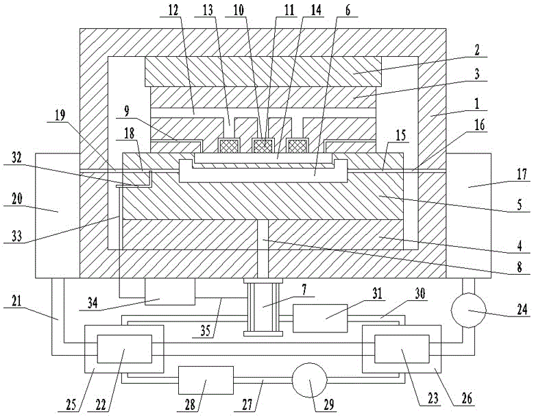
[0010] Such as figure 1 As shown, the automobile grille processing mold includes: a frame 1, an upper mold base 2 is arranged on the inner upper end of the frame 1, and a molding fixed mold 3 is arranged on the upper mold base 2, and a molding die 3 is arranged on the upper mold base 2. The lower end of the frame 1 is provided with a lower mold base 4, on which a forming movable mold 5 cooperating with the forming fixed mold 3 is arranged, and between the forming fixed mold 3 and the forming movable mold 5 is provided with The grid cavity 6 is provided with a jacking cylinder 7 at the lower end of the frame 1, and the piston rod 8 of the jacking cylinder 7 passes through the frame 1 and the lower mold base 4 and the forming movable mold

[0011] 5, and injection channels 9 are symmetrically arranged in the molding fix...


PUM


Abstract

The invention discloses an automobile grille machining mold which comprises a machine frame. An upper mold base is arranged at the upper end inside the machine frame. A fixed forming mold is arranged on the upper mold base. A lower mold base is arranged at the lower end of the machine frame. A movable forming mold mutually matched with the fixed forming mold is arranged on the lower mold base. A grille cavity is formed between the movable forming mold and the fixed forming mold. A jacking air cylinder is arranged at the lower end of the machine frame. A piston rod of the jacking air cylinder penetrates through the machine frame and the lower mold base and is connected with the movable forming mold. Injection molding channels are symmetrically arranged in the portions, at the upper ends of the two sides of the grille cavity, inside the fixed forming mold. The injection molding channels are connected with an injection molding device. A plurality of sintered metal block storage grooves are evenly formed in the portion, at the upper end of the grille cavity, of the fixed forming mold. Sintered metal blocks are embedded in the sintered metal block storage grooves. A main exhaust channel is arranged at the upper end of the fixed forming mold in a penetrating mode.

Description

technical field [0001] The invention relates to a mold, in particular to an automobile grid processing mold. Background technique [0002] Automobile grille is a kind of auto parts. In the production process, automobile grille is generally processed by injection mold. The existing injection molding processing molds mainly have the following shortcomings when processing grilles: 1. The existing processing molds are generally One end feeds and the other end exhausts. This processing method has slow injection molding efficiency and uneven injection molding. Second, using the above-mentioned one-end feeding and the other-end exhausting structure for injection molding will easily cause the gas in the cavity to not be discharged in time, resulting in processing and molding. There are pores in the grille and even lead to partial scorching, flow marks, material shortage, air inhalation and other phenomena in the grille under high temperature and high pressure gas, resulting in defec...

Claims


Application Information

Patent Timeline
Patent Type & Authority Applications(China)
IPC IPC(8): B29C45/26B29C45/34B29C45/73
CPCB29C45/26B29C45/345B29C45/7312
Inventor 孙从贵
Owner JIANGSU YUYAN MOLD IND
Why Eureka
Try Eureka