
Rod support structure lifting device for special-shaped spacecraft

A lifting device and supporting structure technology, applied in the direction of transportation and packaging, load hanging components, etc., can solve the problems such as the inability to use lifting devices, and achieve the effects of uneven lifting force, good use effect, and lightweight design

Inactive Publication Date: 2018-03-16
BEIJING INST OF SPACECRAFT ENVIRONMENT ENG
View PDF3 Cites 0 Cited by
  • Summary
  • Abstract
  • Description
  • Claims
  • Application Information

AI Technical Summary

Problems solved by technology

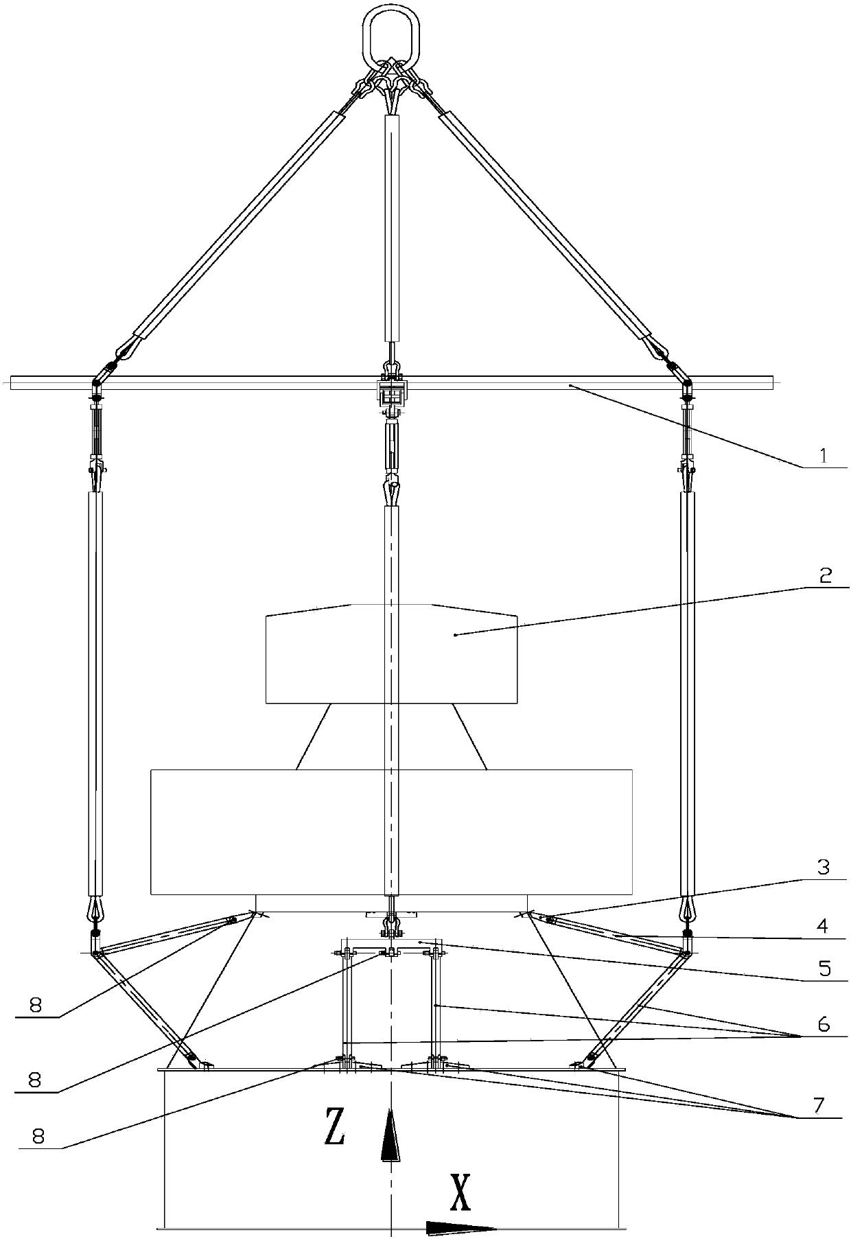
In contrast, a special-shaped spacecraft adopts a multi-vehicle series configuration design, which has the configuration characteristics of a wide top and a narrow middle. The support cabin in the middle adopts a tapered structure with a small top and a large bottom. The lifting points are distributed on the upper and lower end surfaces of the support cabin, and are shrunk within the envelope of the main structure of the spacecraft (such as figure 1 As shown), the position and interface form of the lifting point are completely different from those of the existing spacecraft, and the existing lifting device cannot be used. It is necessary to develop a new special lifting device according to the structural characteristics of the special-shaped spacecraft to lift the spacecraft. Points extend to the outside of the main structure, and achieve uniform loading of each lifting point to solve the lifting problem of special-shaped spacecraft

Method used


Image

  • Rod support structure lifting device for special-shaped spacecraft

Examples


Embodiment Construction

[0016] The following is a specific implementation manner of the content of the present invention, and the content of the present invention will be further clarified through the specific implementation mode below. Of course, the following specific embodiments are described only to illustrate different aspects of the present invention, and should not be construed as limiting the scope of the present invention.

[0017] like figure 1 As shown, a lifting device for a rod support structure of a special-shaped spacecraft according to a specific embodiment of the present invention includes a suspension assembly 1, an upper end frame connection block 3, an upper strut 4, a subbeam 5, a lower strut 6, and a lower end Frame connection block 7, bearing pin 8. First of all, four groups of strut assemblies are arranged symmetrically in the two diameter directions of the cross of the special-shaped spacecraft 2, and each set of strut assemblies includes an upper end frame connection block ...


PUM


Abstract

The invention discloses a lifting device for a rod support structure of a special-shaped spacecraft. The lifting device comprises four sets of support rod modules and lifting modules; each set of support rod modules includes an upper end frame connecting block, an upper support rod, a secondary beam, two lower support rods and two lower end frame connecting blocks; the four sets of support rod modules are respectively arranged in the cross diameter directions of the peripheral direction of the special-shaped spacecraft; the support rod modules and a support cabin form a stable tetrahedron rod support structure; and mounting angles of the upper support rods, the lower support rods and the secondary beams are optimized to change bearing states of an upper end frame lifting point and a lower end frame lifting point of the support bin of the special-shaped spacecraft. The lifting device realizes the force balance function, is uniform in stress of multiple lifting points, adopts the rod support structure to integrate multiple dispersed lifting points with large span in one point through the support rods, reasonably designs the placing angles of the support rods to realize uniform bearing of all the lifting points, fully exerts the structure performance of the special-shaped spacecraft, and extends the spacecraft lifting points out of a main structure envelope through the support rods.

Description

technical field [0001] The invention belongs to the technical field of spacecraft hoisting tooling, and in particular relates to a lifting device for a rod support structure used for special-shaped spacecraft. Background technique [0002] The lifting device is a necessary device to realize the transition between different stations during the final assembly process of the spacecraft. In order to reduce the design difficulty and installation risk of the lifting device, the lifting point of the spacecraft is usually set on the top or outside the envelope of the main structure of the spacecraft. The lifting device can be connected to the spacecraft only through pins, screws or simple adapters. The connection is fixed. In contrast, a special-shaped spacecraft adopts a multi-vehicle series configuration design, which has the configuration characteristics of a wide top and a narrow middle. The support cabin in the middle adopts a tapered structure with a small top and a large bot...

Claims


Application Information

Patent Timeline
Patent Type & Authority Patents(China)
IPC IPC(8): B66C1/22B66C1/62
Inventor 李晓欢易旺民郑圣余鲍晓萍翟怡陈启威郭大宝唐赖颖祝亚宏刘福全
Owner BEIJING INST OF SPACECRAFT ENVIRONMENT ENG
Learn More