Lifting stand column with ultra-low installation distance

A technology of lifting column and installation distance, which is applied to the legs of general furniture, lifting devices, household appliances, etc., can solve the problems of low installation distance and the installation distance of lifting column cannot be further reduced.

Active Publication Date: 2017-02-22
ZHEJIANG JIECHANG LINEAR MOTION TECH
View PDF9 Cites 5 Cited by
  • Summary
  • Abstract
  • Description
  • Claims
  • Application Information

AI Technical Summary

Problems solved by technology

[0004] The purpose of the present invention is to provide a lifting column with an ultra-low installation distance to solve the technical problem that the installation distance of the existing lifting column cannot be further reduced

Method used


Image

  • Lifting stand column with ultra-low installation distance
  • Lifting stand column with ultra-low installation distance

Examples


Embodiment 1

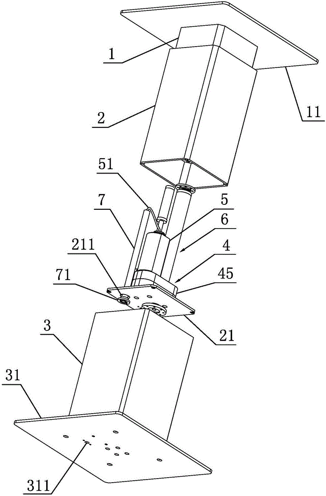
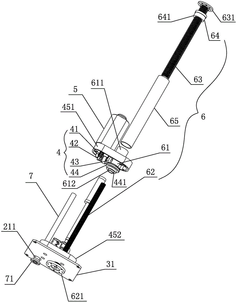
[0020] like figure 1 and figure 2 As shown, the present invention provides a lifting column with an ultra-low installation distance, including an inner tube 1, a middle tube 2 sleeved outside the inner tube 1 and slidingly fitted with the inner tube 1, and a middle tube 2 sleeved outside the middle tube 2 and connected to the inner tube 1. The outer tube 3 that the middle tube 2 slides fits, the bottom end of the middle tube 2 is connected with a middle plate 21, the bottom end of the outer tube 3 is connected with a bottom plate 31, and the middle tube 2 is provided with a transmission mechanism 4 installed on the middle plate 2, The drive motor 5 that is in transmission with the input end of the transmission mechanism 4 and the drive mechanism 6 that is in transmission cooperation with the output end of the transmission mechanism 4 and can drive the outer tube 3 and the inner tube 1 while reciprocatingly sliding relative to the middle tube 2, the drive motor 5 passes throug...

Embodiment 2

[0030] like figure 1 As shown, the difference between this embodiment and Embodiment 1 is that the sleeve rod 7 is an injection tube molded on the outer sheath of the power cord 51. The injection tube has a certain hardness, and the power cord can also be inserted along the middle The tube is supported axially.


PUM


Abstract

The invention discloses a lifting stand column with the ultra-low installation distance, and belongs to the technical field of lifting devices. The technical problem that the installation distance of an existing lifting stand column cannot be further reduced is solved. For solving the problem, the lifting stand column mainly comprises an inner pipe, a middle pipe arranged outside the inner pipe in a sleeving manner and being in sliding fit with the inner pipe and an outer pipe arranged outside the middle pipe in a sleeving manner and being in sliding fit with the middle pipe; the bottom end of the middle pipe is connected with a middle plate, the bottom end of the outer pipe is connected with a bottom plate, a transmission mechanism mounted on the middle plate, a drive motor being in transmission fit with the input end of the transmission mechanism and a drive mechanism which is in transmission fit with the output end of the transmission mechanism and can drive the outer pipe and the inner pipe to do reciprocating sliding relative to the middle pipe at the same time are arranged in the middle pipe, the drive motor is provided with a power line connected with a power source, a casing rod arranged outside the power line in a sleeving manner and a first through hole allowing the power line to stretch out of the bottom plate are arranged on the bottom plate, and a second through hole is formed in the middle plate; the bottom end of the casing rod is fixed to the bottom plate, and the top end of the casing rod penetrates the first through hole to stretch into the middle pipe.

Description

technical field [0001] The invention belongs to the technical field of lifting devices and relates to a lifting column with an ultra-low installation distance. Background technique [0002] As a lifting device, the lifting column is widely used on various lifting platforms, such as lifting tables, liftable tatami, etc. At present, the existing lifting columns generally include inner tubes, middle tubes and outer tubes that are nested with each other. The driving mechanism is driven by the driving motor arranged in the lifting column to make the inner tube and the outer tube reciprocally slide relative to the middle tube, thereby realizing the lifting function. [0003] In the prior art, in order to reduce the installation distance of the lifting column to obtain a larger lifting range, the drive motor and the drive mechanism are installed on the middle plate at the bottom of the middle tube, and the power line of the motor passes through the middle plate and the inner plate ...

Claims


Application Information

Patent Timeline
Patent Type & Authority Applications(China)
IPC IPC(8): B66F13/00A47B9/00A47B91/00E04F15/024
CPCA47B9/00A47B91/00B66F13/00E04F15/02464
Inventor 陆小健胡仁昌程云山裘凯峰
Owner ZHEJIANG JIECHANG LINEAR MOTION TECH
Why Eureka
Try Eureka