
Auxiliary vacuumizing and automatic mud jacking integrated machine for railways
An all-in-one, automatic technology, applied in the erection/assembly of bridges, bridges, buildings, etc., can solve the problems of not realizing automatic control, affecting construction quality, and large impact of manual intervention, and improving the degree of automatic operation and control. The effect of measuring accuracy and weighing accuracy is not reduced
- Summary
- Abstract
- Description
- Claims
- Application Information
AI Technical Summary
Problems solved by technology
Method used
Image

Examples
Embodiment 1
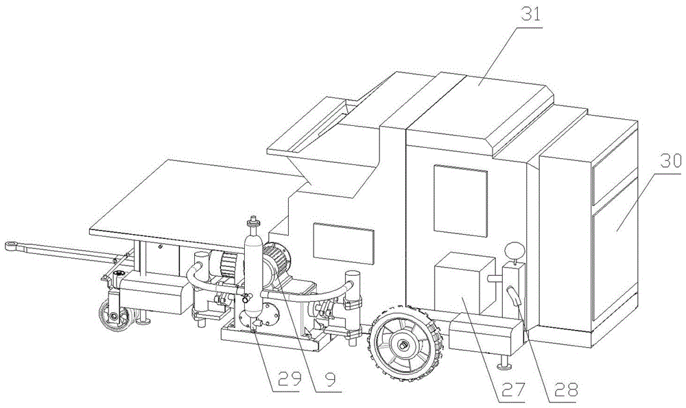
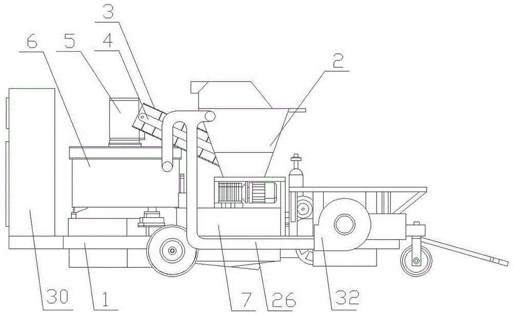
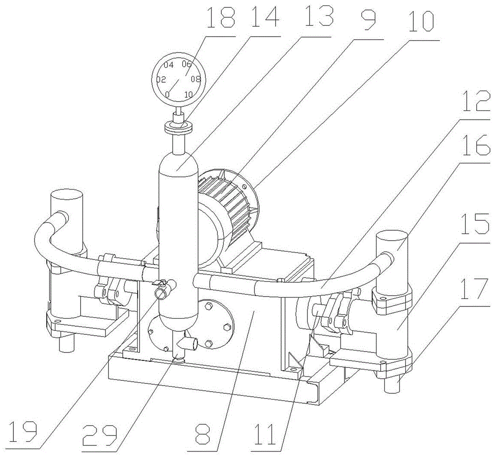
[0044] Such as Figure 6 As shown, the grouting end of the pipeline of the prestressed concrete beam is also provided with an air release pipe 33 . The slurry outlet end of the pipeline of the prestressed concrete beam is provided with a slurry outlet pipe 34 . The vacuum pipe 28, the air release pipe 33, and the grout outlet 29 are all sealed and connected to the pipes of the prestressed concrete beam, and the pipes are respectively provided with corresponding valves. The vacuuming and grouting process of embodiment one are as follows: check the valve situation of the pipeline of the prestressed concrete beam, ensure that the grouting outlet 29, the vacuum pipe 28, the air release pipe 33, and the grouting pipe 34 are all tightly connected with the pipeline, Form a sealed state, and the initial state of each valve is closed; open the valve of the vacuum tube 28 and start the vacuum pump 27 through the PLC assembly electric control box 30, and vacuumize the pipeline. When the...
Embodiment 2
[0046] Such as Figure 7 As shown, the slurry outlet end of the pipeline of the prestressed concrete beam is provided with a slurry outlet pipe 34 . The vacuum pipe 28 and the grout outlet 29 are both sealed and connected to the pipes of the prestressed concrete beams, and the pipes are respectively provided with corresponding valves. The vacuuming and grouting process of embodiment two are as follows: check the valve situation of the pipeline of the prestressed concrete beam, ensure that the grouting outlet 29, the vacuum pipe 28, the air release pipe 33, and the grouting pipe 34 are all tightly connected with the pipeline, Form a sealed state, and the initial state of each valve is closed; open the valve of the vacuum tube 28 and start the vacuum pump 27 through the PLC assembly electric control box 30, and vacuumize the pipeline. When the vacuum in the pipeline is stable at the standard technical requirements When within the range, close the valve of the vacuum tube 28, di...
PUM
 Abstract
Description
Claims
Application Information