Delayed water retaining device for underground garage

A technology of a water blocking device and a delay device, which is applied to door/window protection devices, buildings, building components, etc., can solve problems such as impossibility for vehicles to pass, affecting the passage of vehicles, etc., so as to achieve simple and reliable delay devices, convenient for vehicles to pass, Set up simple effects

Active Publication Date: 2018-11-13
NANJING JUNLI TECH
View PDF6 Cites 0 Cited by
  • Summary
  • Abstract
  • Description
  • Claims
  • Application Information

AI Technical Summary

Problems solved by technology

[0004] The problem with the above-mentioned device is: when the device is installed on the horizontal section of the garage entrance and exit, the position of the inlet and outlet holes 51 on the water-facing surface of the base 5 is too low. Once water comes, it will enter the water storage chamber and lift the front end of the panel to make vehicles impassable
[0005] Therefore, the problem in the prior art is: in the case of a small amount of water accumulation, the water retaining device of the underground garage blocks the entrance passage prematurely, which affects the passage of vehicles

Method used


Image

  • Delayed water retaining device for underground garage
  • Delayed water retaining device for underground garage
  • Delayed water retaining device for underground garage

Examples


Embodiment 1

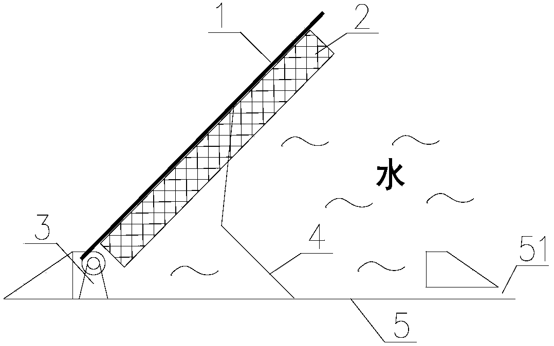
[0023] Embodiment one, such as Figure 4 As shown, as a preferred solution, the delay device 7 is formed as follows: the water inlet hole 51 is a grid, which is arranged on the upper surface of the water storage chamber 5 and is flush with the cover plate 1 of the water storage chamber.

[0024] In this solution, on the one hand, the water inlet hole 51 is placed above the water retaining device, and on the other hand, the water inlet hole is changed into a water inlet grille.

[0025] Its advantages include:

[0026] 1. The delayed opening of the cover plate of the water storage chamber has been realized. Only when the water level at the mouth of the garage is higher than the upper edge of the water storage chamber 5, can the water overflow the water storage chamber 5 and enter the cavity through the water inlet grille water inlet 51 to open the water storage chamber cover plate 1, thereby "making the storage The water chamber cover plate 1 only opens upward when the water ...

Embodiment 2

[0029] Embodiment two, such as Figure 5 As shown, as another preferred solution, the delay device 7 is formed in this way: it also includes a drainage hole 52 placed at the rear end of the water storage chamber 5, the drainage capacity of the drainage hole 52 is not greater than the water blocking threshold, and the water inlet hole The water inlet capacity of 51 is greater than the drainage capacity of drain hole 52. At this time, the water inlet hole 51 is located at the front end of the water storage cavity 5 .

[0030] In order to adapt to different application scenarios, that is, to set different water blocking thresholds, as a further improvement, the drainage hole 52 is provided with a water volume adjustment mechanism. As a further improvement, when the cover plate 1 of the water storage chamber is opened at a certain angle, the water volume regulating mechanism can automatically or manually close the drain hole 52 .

[0031] Only when the water inflow is greater th...

Embodiment 3

[0032] Embodiment three, such as Figure 6 As shown, as a more preferred solution, the water inlet hole 51 is a grille, which is arranged on the upper surface of the water storage chamber 5, flush with the water storage chamber cover plate 1, and also includes a drain hole placed at the rear end of the water storage chamber 5 52. The drainage capacity of the drainage hole 52 is not greater than the water blocking threshold, and the water intake capacity of the water inlet hole 51 is greater than the drainage capacity of the drainage hole 52. In order to adapt to different application scenarios, that is, to set different water blocking thresholds, as a further improvement, the drainage hole 52 is provided with a water volume adjustment mechanism. As a further improvement, when the cover plate 1 of the water storage chamber is opened at a certain angle, the water volume regulating mechanism can automatically or manually close the drain hole 52 .

[0033] Only when the water inf...


PUM


Abstract

The invention discloses a time-delay water retaining device for an underground garage. The time-delay water retaining device comprises a water storage cavity (5) and a water storage cavity cover plate (1). The rear end of the water storage cavity cover plate (1) is hinged to the water storage cavity (5) through a hinge (3), and is matched with the water storage cavity (5) in a closed manner. The time-delay water retaining device also comprises a water inlet hole (5), and when water enters the water storage cavity (5), a floating body (2) upwards opened at the front end of the water storage cavity cover plate (1) can be fixedly arranged on the lower surface of the water storage cavity cover plate (1). The time-delay water retaining device also comprises a time-delay device (7), and the time-delay device (7) enables the water storage cavity cover plate (5) to be opened upwards only when the water quantity at the front end of the water storage cavity (5) reaches a water retaining threshold value. According to the time-delay water retaining device for the underground garage disclosed by the invention, a water retaining plate is opened only when the water quantity is large so as to facilitate vehicle passing. .

Description

technical field [0001] The invention belongs to the technical field of water retaining equipment at the mouth of an underground building, in particular to a time-delayed water retaining device for an underground garage that is convenient for passage. Background technique [0002] In recent years, the torrential rains and extra-heavy rains have caused underground buildings, such as underground garages, to flood in a large amount, causing vehicles and property to be flooded and causing huge losses. In addition to enhancing the drainage capacity of underground buildings, it is also an effective way to block rainwater. [0003] Chinese invention patent application "An automatic water retaining device" (application number: 201410395552.7, publication date: 2014.10.29) discloses an automatic water retaining device, such as figure 1 shown. It includes a panel 1, a base 5, and a hinged seat 3 arranged at one end of the base 5. One end of the panel 1 is hinged to the hinged seat 3,...

Claims


Application Information

Patent Timeline
Patent Type & Authority Patents(China)
IPC IPC(8): E06B9/00
CPCE06B9/00E06B2009/007
Inventor 范良凯徐才奎
Owner NANJING JUNLI TECH
Why Eureka
Try Eureka