
A method for realizing gear shifting process in vehicle drive train

A technology for power trains and vehicles, applied in transmission control, components with teeth, belts/chains/gears, etc., can solve problems such as multiple shift times, achieve the effect of mild speed synchronization and save shift time

Inactive Publication Date: 2020-06-19
AVL LIST GMBH
View PDF9 Cites 0 Cited by
  • Summary
  • Abstract
  • Description
  • Claims
  • Application Information

AI Technical Summary

Problems solved by technology

The disclosed method has the disadvantage that indirect shifting requires significantly more shifting time than direct shifting

Method used


Image

  • A method for realizing gear shifting process in vehicle drive train
  • A method for realizing gear shifting process in vehicle drive train
  • A method for realizing gear shifting process in vehicle drive train

Examples


Embodiment Construction

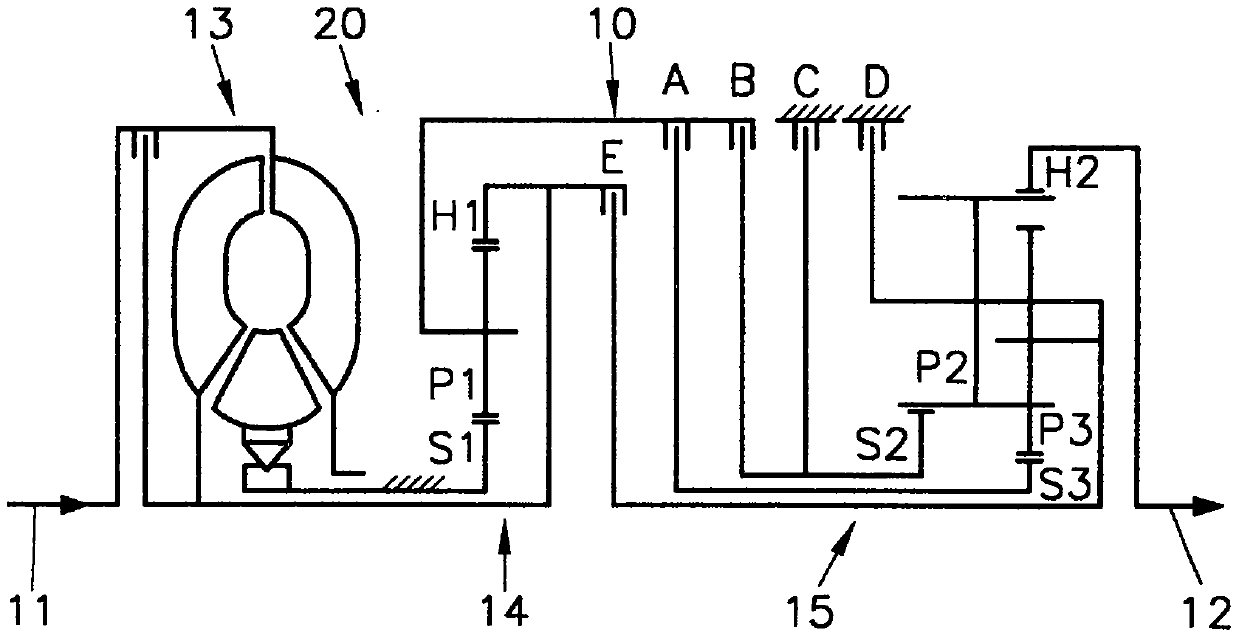
[0030] figure 1 Shown is a motor vehicle drive train 20 arranged between an input shaft 11 and an output shaft 12 with a motor vehicle transmission 10 and a torque converter 13 , which drive train 20 is suitable for carrying out the method according to the invention. A drive machine, not further shown, such as an internal combustion engine, is connected to the input shaft 11 , and a vehicle output, not further shown, is connected to the output shaft 12 . The vehicle transmission 10 formed as an automatic transmission, for example, has a first planetary gear train 14 and a second planetary gear train 15, a first shifting element A, a second shifting element B, a third shifting element C, a fourth shifting element D, and a fifth shifting element. Shifting element E, wherein the second planetary gear train 15 is formed as a Ravigneaux gear set. In this exemplary embodiment, the shift elements A, B, E are formed as shifting clutches, and the shift elements C, D are formed as brak...


PUM


Abstract

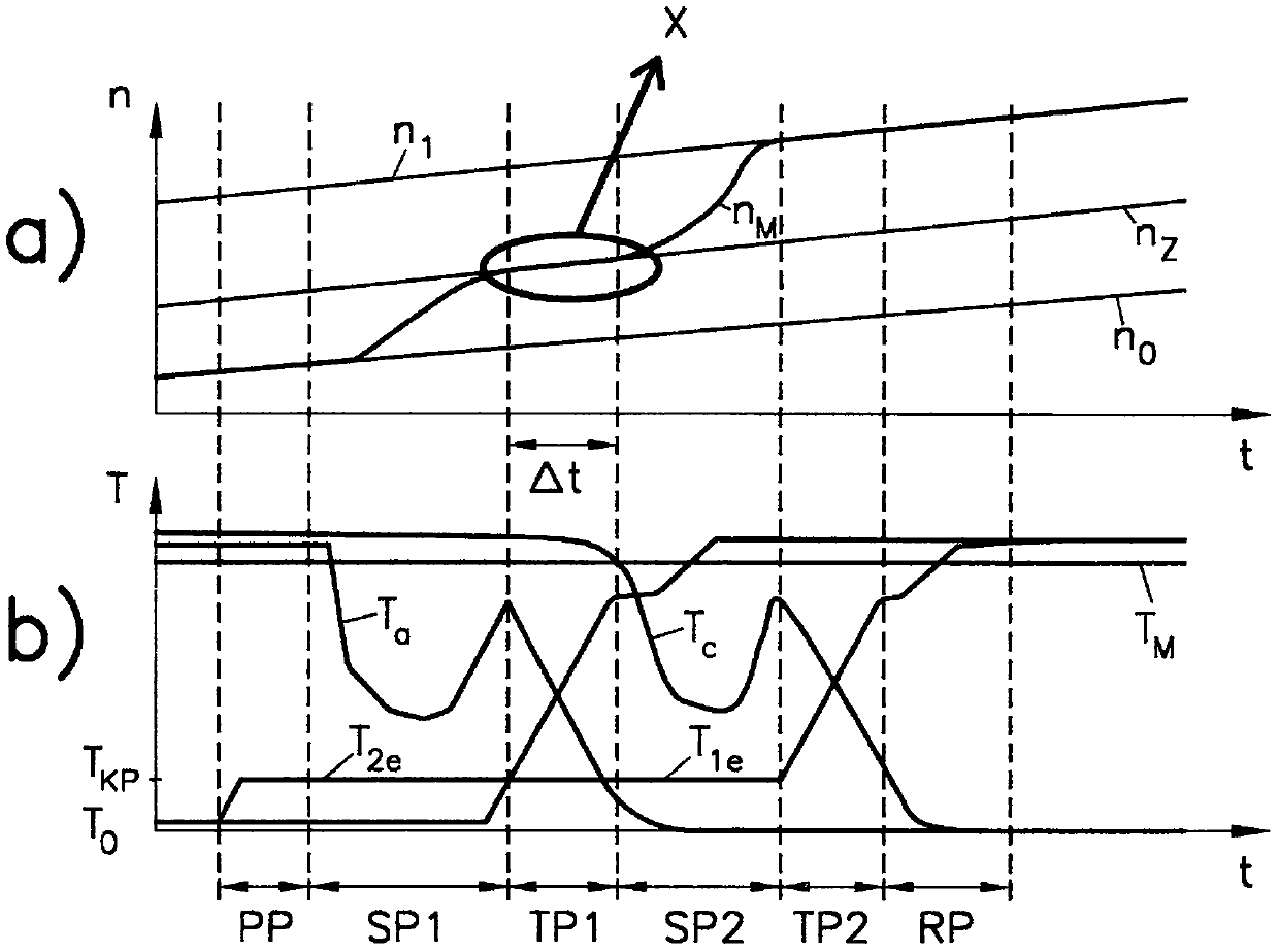
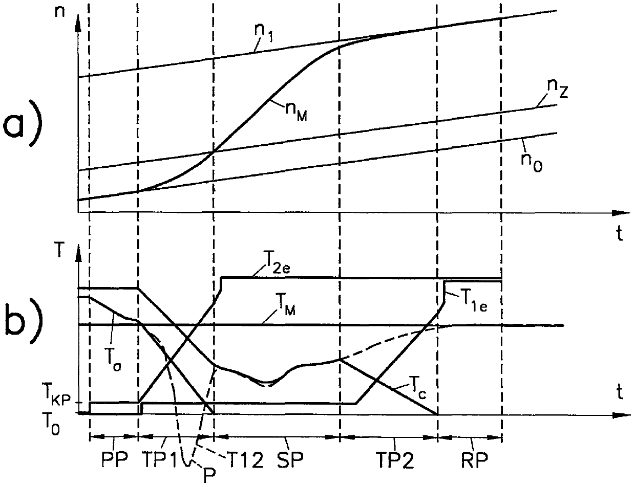
The invention relates to a method for gear shifting in a vehicle power train (20). The vehicle power train comprises a vehicle transmission (10), an output shaft (11) of a vehicle power train (17) is connected with an output shaft (12) through at least two switching elements at different gear positions. During at least one indirect shifting operation from a source gear to a target gear in a first torque stage, the rotational speed (nM) of an engine and the rotational speed (n1) of the target gear are synchronized in a rotational speed phase (SP) following a first torque phase (TP1) of a torque transfer from at least one outgoing shifting element to at least one incoming first shifting element, and a torque transfer from a continuous gear element to a retracting second gear element is performed in a second torque phase (TP2) following the speed phase (SP). In order to achieve short shifting times in the case of indirect shifting operations, it is specified that the synchronization between the rotational speed (n1) of the target gear and the engine speed (nM) begins at or at the end of the first torque phase (TP1).

Description

technical field [0001] The invention relates to a method for implementing a gearshift process in a vehicle drive train with a vehicle transmission, wherein the input shaft of the vehicle drive train is connected to the output shaft via different gears via at least two shifting elements, wherein at least During an indirect shift from source gear to target gear in the first torque phase, the torque transmission from the outgoing shifting element to the incoming first shifting element achieves engine Synchronization between the rotational speed and the rotational speed of the target gear, and a torque transmission from the continuing shift element to the entering second shift element in a second torque phase occurring after the speed phase. [0002] As incoming shifting elements here are shifting elements that are opened in the source gear and closed in the target gear, which are engaged (that is, closed) during at least one torque phase of the gearshift and are in the target gea...

Claims


Application Information

Patent Timeline
Patent Type & Authority Patents(China)
IPC IPC(8): F16H61/26F16H61/00
CPCF16H61/04F16H61/08F16H61/00F16H61/26F16H2061/0096F16H61/0437F16H61/06F16H2061/062
Inventor M·尤加
Owner AVL LIST GMBH
Learn More