Counterweight type rotary bracket, holder comprising bracket and counterweight method

A technology of rotating bracket and counterweight, applied in the field of gimbal, can solve problems such as collision between equipment and power mechanism, blocking of equipment line of sight, affecting the normal operation of motor, etc., so as to avoid blocking and increase the shooting range.

Active Publication Date: 2017-02-22
SHENZHEN SNOPPA TECH CO LTD
View PDF8 Cites 5 Cited by
  • Summary
  • Abstract
  • Description
  • Claims
  • Application Information

AI Technical Summary

Problems solved by technology

[0002] At present, most of the cloud platforms on the market are three-axis structure platforms, such as a handheld three-axis platform with a patent number of (CN201410612517), the structure of which is three orthogonally distributed motors in space. , the three motors respectively control the X-axis motor for pitching motion, the Y-axis motor for controlling rolling motion, and the Z-axis motor for controlling yaw motion. The gimbal comes up to meet the balance of the gimbal’s center of gravity. The counterweight method relies on manually adding counterweight objects. In addition, the three motors provide power and control through the same wire. As the motor rotates, the wire will be dragged , will affect the normal operation of the motor and reduce the stability of the gimbal; since the rotation axes of the three motors pass through the equipment on the equipment rack of the gimbal, when moving to a specific state, it is easy to cause the line of sight of the equipment to be blocked and the equipment to be separated from the equipment. Collision between powertrains

Method used


Image

  • Counterweight type rotary bracket, holder comprising bracket and counterweight method
  • Counterweight type rotary bracket, holder comprising bracket and counterweight method
  • Counterweight type rotary bracket, holder comprising bracket and counterweight method

Examples


Embodiment Construction

[0037] In order to fully understand the technical content of the present invention, the technical solutions of the present invention will be further introduced and illustrated below in conjunction with specific examples, but not limited thereto.

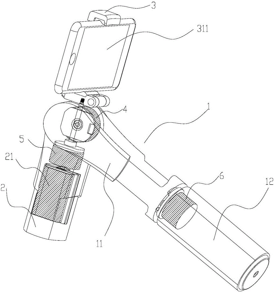
[0038] Such as figure 1 As shown, a counterweight type rotating bracket of the present invention includes a bracket, and a movable arm 2 that is rotatably coupled with the bracket; the middle section of the movable arm 2 is rotatably coupled with the bracket, and one end of the movable arm 2 is provided with an image acquisition device 311 for installation Clamping part 3, the other end of movable arm 2 is provided with counterweight mechanism 21, in the present embodiment, clamping part 3 is arranged on the upper end of movable arm 2, and counterweight mechanism 21 is located at the lower end of movable arm 2; 311 includes devices such as mobile phones, cameras, video cameras, and scanners.

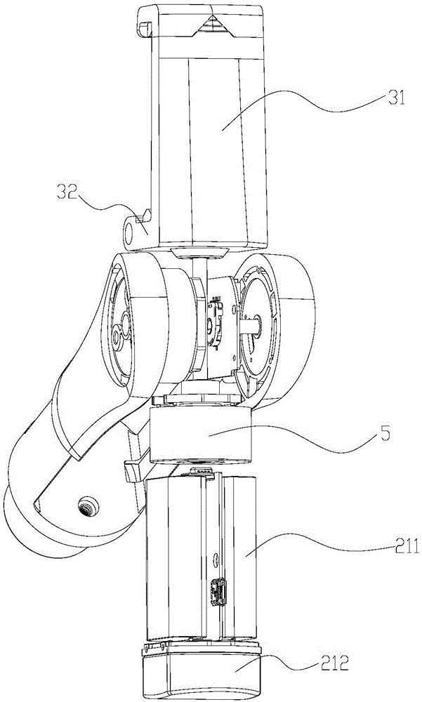
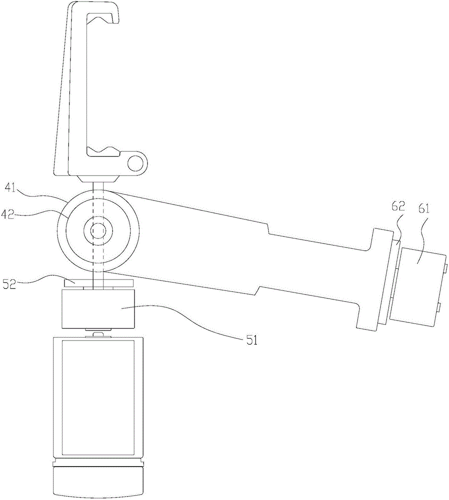
[0039] Such as figure 1 , figure 2 A...


PUM


Abstract

The invention discloses a counterweight type rotary bracket, a holder comprising the bracket and a counterweight method. The bracket comprises a bracket body and a moving arm rotationally connected with the bracket body; the middle section of the moving arm is rotationally connected with the bracket body; a clamping part for mounting of image acquisition equipment is arranged at one end of the moving arm; and a counterweight mechanism is arranged at the other end of the moving arm. With the counterweight type rotary bracket, the holder comprising the bracket and the counterweight method, the counterweight mechanism is arranged at the other end of the moving arm, the moving arm and the bracket body can realize gravity center balancing by adjusting the counterweight mechanism, meanwhile, a battery, a circuit board and an electronic device of the holder can be used as part of the counterweight mechanism or the whole counterweight mechanism, and the multi-purpose effect is realized; and besides, the image acquisition equipment is arranged at one end of the moving arm through the clamping part and can rotate by 360 degrees, the shooting range is enlarged, and meanwhile, blocking of shooting sight is avoided.

Description

technical field [0001] The invention relates to a cloud platform, more specifically a counterweight type rotating bracket, a platform composed of the platform and a counterweight method. Background technique [0002] At present, most of the cloud platforms on the market are three-axis structure platforms, such as a handheld three-axis platform with a patent number of (CN201410612517), the structure of which is three orthogonally distributed motors in space. , the three motors respectively control the X-axis motor for pitching motion, the Y-axis motor for controlling rolling motion, and the Z-axis motor for controlling yaw motion. The gimbal comes up to meet the balance of the gimbal’s center of gravity. The counterweight method relies on manually adding counterweight objects. In addition, the three motors provide power and control through the same wire. As the motor rotates, the wire will be dragged , will affect the normal operation of the motor and reduce the stability of...

Claims


Application Information

Patent Timeline
IPC IPC(8): F16M11/12F16M11/18
CPCF16M11/121F16M11/18F16M2200/041
Inventor 周继双温勇王健周杰凌
Owner SHENZHEN SNOPPA TECH CO LTD
Why Eureka
Try Eureka