Range hood provided with cooking fume guide plate

A range hood and smoke deflector technology, which is applied in the field of range hoods to improve the effect of range hoods and solve oil circuit problems

Active Publication Date: 2017-02-22
NINGBO FOTILE KITCHEN WARE CO LTD
View PDF9 Cites 18 Cited by
  • Summary
  • Abstract
  • Description
  • Claims
  • Application Information

AI Technical Summary

Problems solved by technology

However, the lifting mechanism of this range hood drives the straightening plate up and down. Due to the limitation of the oil circuit, the oil cup and the

Method used


Image

  • Range hood provided with cooking fume guide plate
  • Range hood provided with cooking fume guide plate
  • Range hood provided with cooking fume guide plate

Examples


Embodiment 1

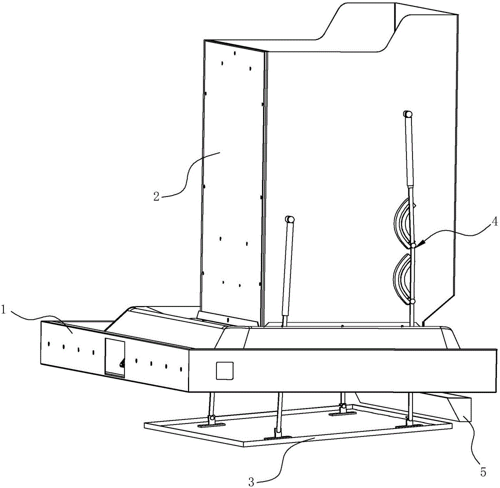
[0036] see Figure 1 to Figure 6 , a range hood with a smoke guide plate, including a smoke collection hood 1 formed with a smoke collection chamber, a fan cover 2 and a smoke guide plate 3, the smoke guide plate 3 can use the existing technology, as described in the background technology , and it is arranged directly below the air inlet opening on the fume collecting hood 1 . The left and right sides of the fan cover 2 are provided with a lifting mechanism 4 for driving the smoke guide plate 3 to rotate and lift. An oil cup 5 is arranged below the smoke collecting hood 1 at the rear side of the smoke guide plate 3 .

[0037] The lifting mechanism 4 includes a first lifting mechanism at the front and a second lifting mechanism at the rear. The first lifting mechanism includes a first push rod 41 and a first shaft sleeve 42. The top of the first shaft sleeve 42 is in contact with the fan cover 2 The side wall of the first push rod 41 is rotatably connected, the upper part of ...

Embodiment 2

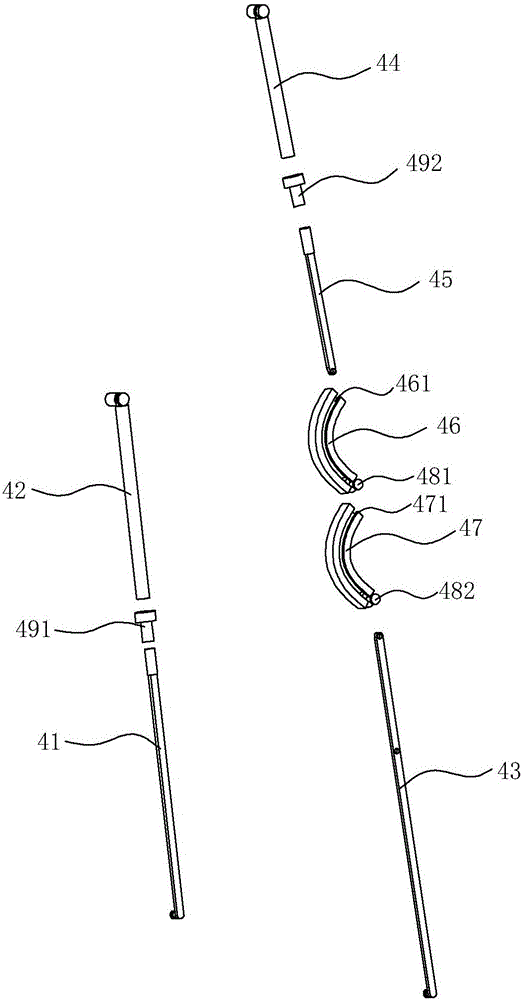
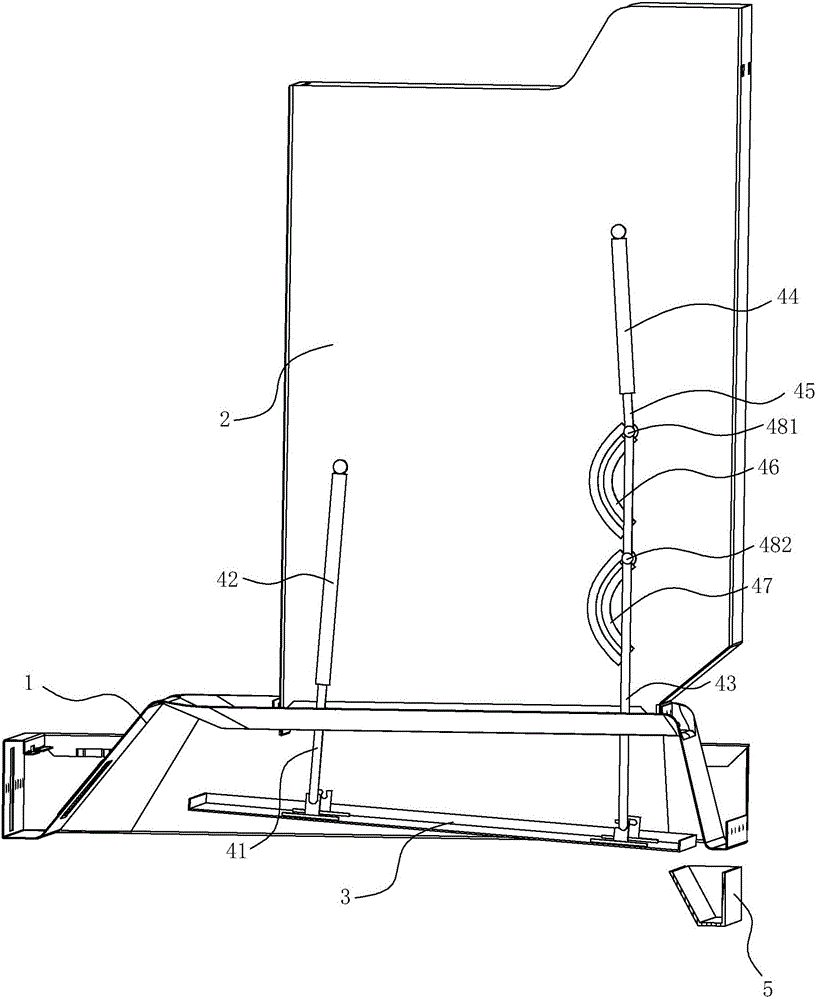
[0043] see Figure 7 ~ Figure 11 , in this embodiment, the difference from the first embodiment above is that the second lifting mechanism includes a second push rod 43, a second bushing 44, a connecting rod 45, a transmission rod 46', and is arranged behind the second push rod 43. The first rocker 47' and the second rocker 48' on the side, the second shaft sleeve 44 is connected with the side wall of the fan cover 2 to keep vertical, the upper part of the connecting rod 45 is inserted in the second shaft sleeve 44, and the connecting rod 45 The lower end of the second push rod 43 is rotatably connected to the upper end of the second push rod 43 through a transmission rod 46 ′, and the lower end of the second push rod 43 is rotatably connected to the rear of the smoke guiding plate 3 . One end of the first rocking bar 47' is rotatably connected with the side wall of the fan cover 2, and the other end is rotatably connected with the upper end of the second push rod 43; one end ...

Embodiment 3

[0046] see Figure 12 to Figure 16 , in this embodiment, the difference from the first embodiment above is that the connecting rod and bushing of the second elevating mechanism are replaced by a gear transmission mechanism, including first gears 44 ″ arranged at intervals up and down, located between two first gears 44 "The second gear 45" between ", and the second push rod 43. The second gear 45" meshes with the two first gears 44' respectively, and the second push rod 43 is eccentric with the two first gears 44" respectively. The positions are connected, the first gear 44" enables the second push rod 43 to move forward and backward during the movement, and keeps the second push rod 43 always vertical during the movement. In this embodiment, the driving mechanism is a motor, which can drive one of the first gears 44" to rotate.

[0047] The movement mode of the smoke guiding plate 3 is as shown in the first and second embodiments.


PUM


Abstract

The invention discloses a range hood provided with a cooking fume guide plate. The range hood comprises a cooking fume collection hood, a fan hood, the cooking fume guide plate, a lifting mechanism and an oil cup, wherein the lifting mechanism is used for driving the cooking fume guide plate to be lifted up and down; the oil cup is arranged below the cooking fume collecting hood and is positioned at the rear side of the cooking fume guide plate; the lifting mechanism comprises a first lifting mechanism and a second lifting mechanism, wherein the first lifting mechanism is used for driving the cooking fume guide plate to rotate and to be lifted up and down with respect to the oil cup; the second lifting mechanism is used for driving the cooking fume guide plate to move forwards and backwards and to be lifted up and down with respect to the oil cup; therefore, the cooking fume guide plate can do a lifting motion in a manner of bypassing the oil cup by virtue of the first lifting mechanism and the second lifting mechanism. Under the driving of the lifting mechanism, the rear end of the cooking fume guide plate is inclined downwards when the cooking fume guide plate is in a contracted state, so that accumulated oil dirt can enter the oil cup via oil leaking holes; when the cooking fume guide plate is in a descending state, the front end of the cooking fume guide plate is inclined downwards, and the oil dirt is accumulated forwards, so that the cooking fume guide plate has a certain oil accumulation function and can bypass the oil cup, the oil cup does not need to move with the cooking fume guide plate, oil line problems are solved as well, and the cooking fume suction effect of the range hood is improved.

Description

technical field [0001] The invention relates to a range hood, in particular to a range hood with a smoke guiding plate. Background technique [0002] At present, the overall installation height of the European-style range hood determines that the range hood is relatively far away from the pan that produces the oil fume, and the negative pressure loss is relatively large. In order to improve the range hood effect of the range hood, people have improved the structure of the range hood, and the usual method is to improve the fan system of the range hood, such as increasing the power of the fan, such as improving the structure of the impeller, etc. etc. Although this improvement can effectively improve the range hood's range hood effect, it needs to improve the structure of the entire fan system, which is not only more complicated, but also cannot improve the distribution of the negative pressure area when the range hood is working, and the negative pressure loss It is still re...

Claims


Application Information

Patent Timeline
IPC IPC(8): F24C15/20
CPCF24C15/2085
Inventor 边乐超何立博陈浩辉茅忠群诸永定李斌
Owner NINGBO FOTILE KITCHEN WARE CO LTD
Why Eureka
Try Eureka