Automatic cable returning and winding displacement equipment for optical cable

An automatic and optical cable technology, applied in the direction of light guides, optics, optical components, etc., can solve the problems of low recovery success rate of optical cable sub-units or optical cable sleeves, easy accumulation of cables, clamped and broken tubes, etc., to achieve improved rowing Excellent wire quality, convenient power source, and stable operation

Active Publication Date: 2017-02-22
YANGTZE OPTICAL FIBRE & CABLE CO LTD
View PDF5 Cites 4 Cited by
  • Summary
  • Abstract
  • Description
  • Claims
  • Application Information

AI Technical Summary

Problems solved by technology

[0002] In the production of twisted optical cables, the traditional helical twisting method has been replaced by SZ twisting (left and right reciprocating twisting); the SZ twisting process speed is high, and the mechanical properties of the optical cable can meet the use, but there will also be faults in the SZ twisting production process. products, at this time, it is necessary to return a section or all of the optical cable subunits to be wound on the casing coil for recovery
[0003] Now every time there is a need for cable unwinding in the workshop, during the unwinding process, the worker manually cuts the yarn piece by piece with a blade, and after releasing it, takes a sleeve reel, and binds the optical cable subunit or the optical cable sleeve that needs to

Method used


Image

  • Automatic cable returning and winding displacement equipment for optical cable
  • Automatic cable returning and winding displacement equipment for optical cable

Examples


Embodiment Construction

[0030] In order to make the object, technical solution and advantages of the present invention clearer, the present invention will be further described in detail below in conjunction with the accompanying drawings and embodiments. It should be understood that the specific embodiments described here are only used to explain the present invention, not to limit the present invention. In addition, the technical features involved in the various embodiments of the present invention described below can be combined with each other as long as they do not constitute a conflict with each other.

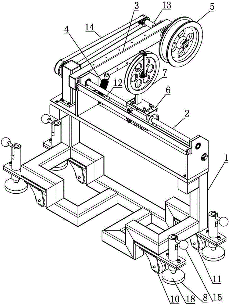
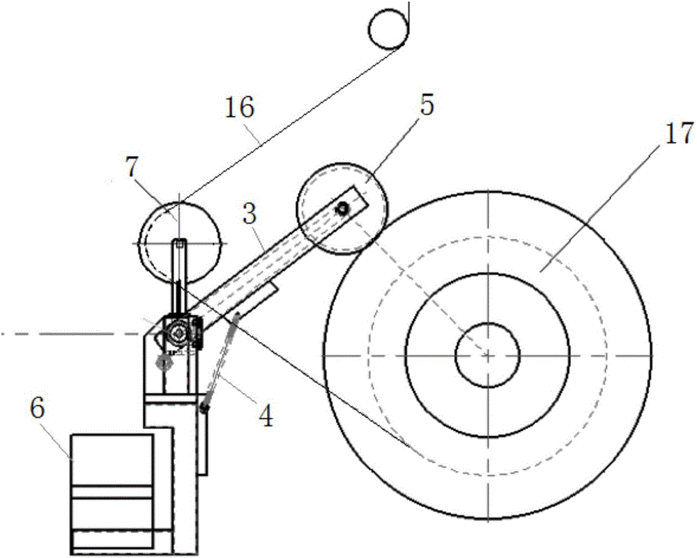
[0031] refer to figure 1 , figure 2 , an automatic cable unwinding device for an optical cable, comprising a frame 1, a polished rod cable arrangement, a swing arm 3, a tension spring 4, a pressure wheel 5 and a transition guide wheel 7, wherein,

[0032] The polished rod cable arranger includes a cable rotating shaft 2 and a moving body 6 that can reciprocate on the cable rotating shaft 2; ...


PUM


Abstract

The invention belongs to the field of take-up equipment of optical cables and discloses automatic cable returning and winding displacement equipment for an optical cable. The automatic cable returning and winding displacement equipment comprises a rack, a polished rod winding displacement device, a swing arm, an extension spring, a pressure roller and a transitional guide wheel, wherein the polished rod winding displacement device comprises a winding displacement rotating shaft and a moving main body; the winding displacement rotating shaft is rotationally arranged on the rack; an intermediate rotating shaft is rotationally arranged on the swing arm; the pressure roller is fixedly arranged on the intermediate rotating shaft; the intermediate rotating shaft is connected with the winding displacement rotating shaft by a driving mechanism; one end of the extension spring is arranged on the swing arm, and the other end of the extension spring is arranged on the rack; the transitional guide wheel is fixedly arranged on the moving main body and the central line of the transitional guide wheel is parallel to that of the winding displacement rotating shaft. The automatic cable returning and winding displacement equipment can be used in production links in batches and is remarkable in effect; a large amount of labor force is reduced, and the winding displacement quality of a recovered optical cable subunit or an optical cable casing pipe is improved.

Description

technical field [0001] The invention belongs to the field of optical cable take-up equipment, and more specifically relates to an automatic optical cable unwinding and arranging equipment. Background technique [0002] In the production of twisted optical cables, the traditional helical twisting method has been replaced by SZ twisting (left and right reciprocating twisting); the SZ twisting process speed is high, and the mechanical properties of the optical cable can meet the use, but there will also be faults in the SZ twisting production process. At this time, a part or all of the optical cable subunit needs to be returned and wound on the sleeve coil for recovery. [0003] Now every time there is a need for cable unwinding in the workshop, during the unwinding process, the worker manually cuts the yarn piece by piece with a blade, and after releasing it, takes a sleeve reel, and binds the optical cable subunit or the optical cable sleeve that needs to be returned to the s...

Claims


Application Information

Patent Timeline
IPC IPC(8): G02B6/44
CPCG02B6/4457
Inventor 李智刚吴斌盛黄杰周珍福
Owner YANGTZE OPTICAL FIBRE & CABLE CO LTD
Why Eureka
Try Eureka