A fully automatic glass drilling machine for glass production and processing

A fully automatic drilling machine technology, applied in the direction of stone processing tools, stone processing equipment, work accessories, etc., can solve the problems of complex operation, low work efficiency, inability to carry out assembly line operation, etc., and achieve the effect of firm structure

Active Publication Date: 2019-09-20
佛山市金耀华玻璃有限公司
View PDF11 Cites 0 Cited by
  • Summary
  • Abstract
  • Description
  • Claims
  • Application Information

AI Technical Summary

Problems solved by technology

But the drilling machine of prior art is more with stand-alone, and the operation of this equipment is more complicated, can't finish the assembly line drilling operation fully automatically, must be put on the glass table machine by several workers, the position that glass needs drilling is moved to The glass drilling can only be done when the bottom of the drill bit is fixed. After drilling a hole, if you need to drill other holes, you need to lift the glass again, fix the glass again, and then carry out the drilling operation until all the drilling is completed according to the above steps. hole
Finally, it is necessary to manually lift the drilled glass from the frame for storage. Automatic transmission and positioning cannot be performed, and assembly line operation cannot be performed. This is extremely inconvenient, and the work efficiency is low, and the processing speed and accuracy cannot meet people's needs.

Method used


Image

  • A fully automatic glass drilling machine for glass production and processing
  • A fully automatic glass drilling machine for glass production and processing
  • A fully automatic glass drilling machine for glass production and processing

Examples


Embodiment Construction

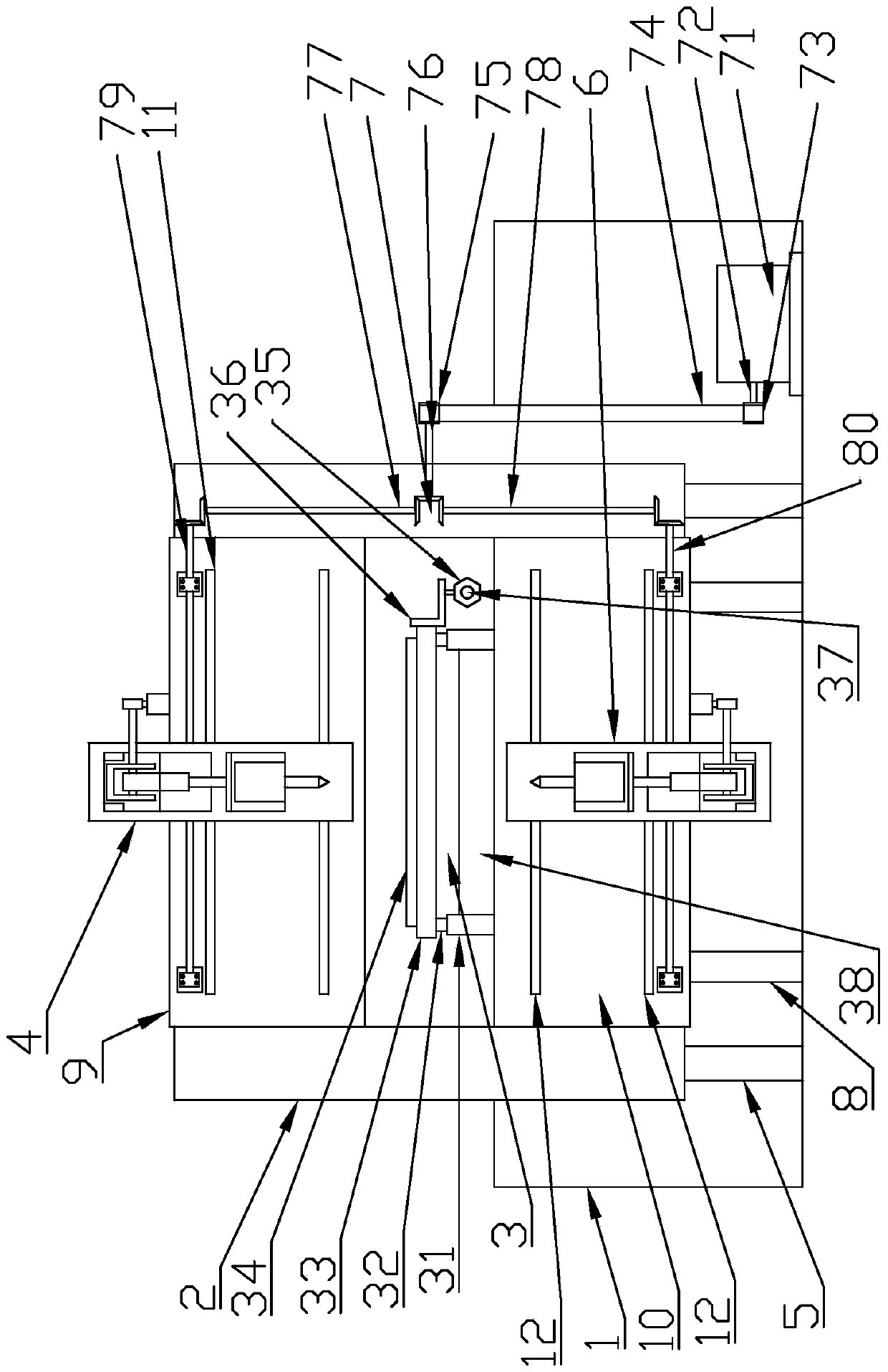
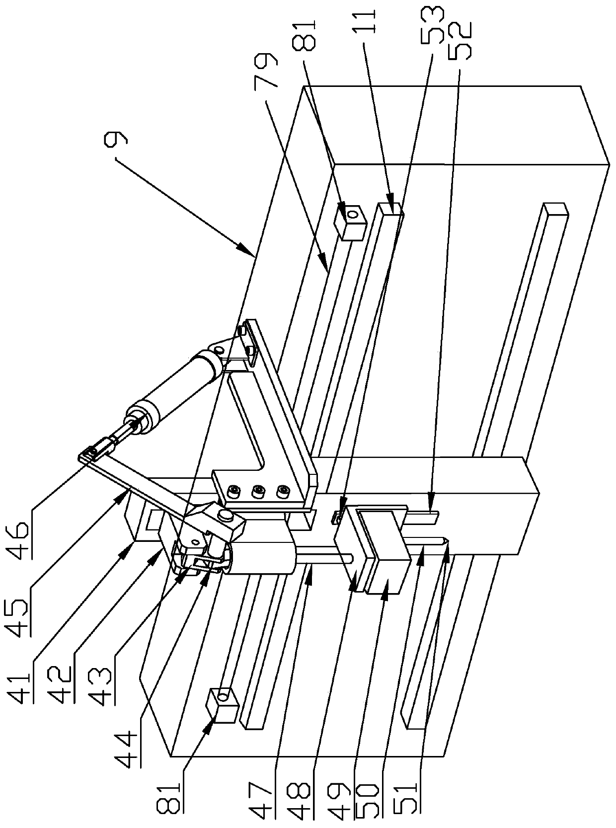
[0035] Such as Figure 1 to Figure 14 As shown, a fully automatic glass drilling machine used in glass production and processing includes a machine base 1 and a conveying device 3 , and the conveying device 3 is located on the machine base 1 . Both sides of conveying device 3 are provided with vertical support frame 2, and the upper end of vertical support frame 2 is provided with upper horizontal frame 9, and upper horizontal frame 9 is fixedly installed on the vertical support frame 2, and the lower end of vertical support frame 2 is provided with A lower cross frame 10 is arranged, and the lower cross frame 10 is fixedly installed in the machine base 1 . The lower end of the lower cross frame 10 is provided with a first support 8 , and the lower end of the vertical support frame 2 is provided with a second support 5 , and both the first support 8 and the second support 5 are fixedly installed in the machine base 1 . The lower cross frame 10 and the vertical support frame 2...


PUM


Abstract

The invention discloses a full-automatic glass drilling machine applied to production and processing of glass. The full-automatic glass drilling machine comprises a machine base and a conveying device. The conveying device is located on the machine base. Vertical supporting frames are arranged on the two sides of the conveying device, an upper transverse frame is arranged at the upper ends of the vertical supporting frames, and a lower transverse frame is arranged at the lower ends of the vertical supporting frames. A first guide rail is arranged on the upper transverse frame and connected with an upper drilling mechanism, and the upper drilling mechanism comprises an upper drilling base and an upper drilling frame. A second guide rail is arranged on the lower transverse frame and connected with a lower drilling mechanism, and the lower drilling mechanism comprises a lower drilling base and a lower drilling frame. Glass workpieces are input from the front end of the machine, then the upper drilling mechanism and the lower drilling mechanism are used for drilling in the middle of the machine, and finally the glass workpieces with drilled holes are output from the rear end of the machine through the conveying device. The upper drilling mechanism is mounted on the upper transverse frame, the lower drilling mechanism is mounted on the lower transverse frame, and a drilling space is formed between the upper drilling mechanism and the lower drilling mechanism and used for drilling operation.

Description

technical field [0001] The invention relates to the technical field of glass production and processing, and specifically refers to a fully automatic glass drilling machine applied to glass production and processing. Background technique [0002] Glass drilling machine is a machine specially used for glass drilling. The glass drilling machine has a large drilling diameter and a large overhang of the machine base, which can process large-size glass. It is an indispensable mechanical equipment in glass processing and production. But the drilling machine of prior art is more with stand-alone, and the operation of this equipment is more complicated, can't finish the assembly line drilling operation fully automatically, must be put on the glass table machine by several workers, the position that glass needs drilling is moved to The glass drilling can only be done when the bottom of the drill bit is fixed. After drilling a hole, if you need to drill other holes, you need to lift t...

Claims


Application Information

Patent Timeline
Patent Type & Authority Patents(China)
IPC IPC(8): B28D1/14B28D7/00
Inventor 应伟苹
Owner 佛山市金耀华玻璃有限公司
Why Eureka
Try Eureka