Glass cabinet support drill jig

A technology for glass cabinets and drilling molds, which is applied in the direction of drilling molds for workpieces, etc., which can solve the problems of casing drilling of glass cabinet supports, etc., and achieve the effect of easy pushing and pushing of pressing blocks, not easy to be damaged, and simple connection methods

Inactive Publication Date: 2016-01-20
重庆新铝城幕墙工程有限公司
View PDF0 Cites 0 Cited by
  • Summary
  • Abstract
  • Description
  • Claims
  • Application Information

AI Technical Summary

Problems solved by technology

[0003] The present invention intends to provide a glass cabinet support drilling mold to solve the problem of drilling the casing of the glass cabinet support

Method used


Image

  • Glass cabinet support drill jig
  • Glass cabinet support drill jig
  • Glass cabinet support drill jig

Examples


Embodiment 1

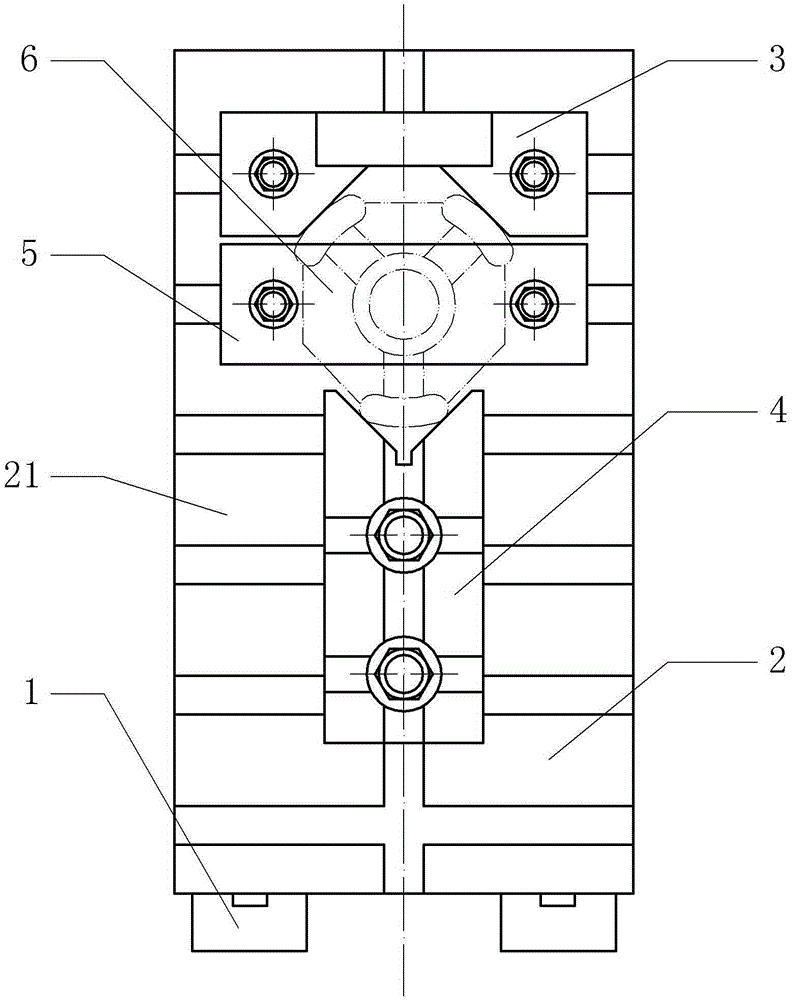
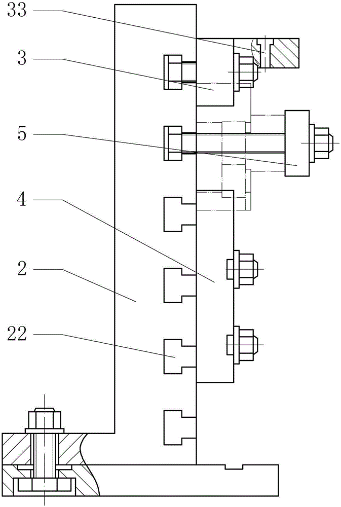
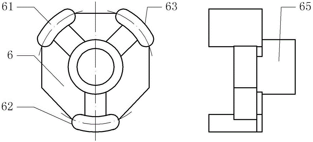
[0017] The embodiment is basically as attached figure 1 , figure 2 , image 3 As shown: the glass cabinet support drilling mold includes a mounting base 2, a fixing part and a pressing part 5; the mounting base 2 is fixedly connected to the vertical drilling machine workbench 1 by bolts, and the mounting base 2 has a vertical and horizontal mounting surface 21, The mounting surface 21 is provided with a T-shaped slot 22 in which the vertical direction and the horizontal direction alternate. The fixed part includes a fixed seat 3 and a push block 4. The fixed seat 3 is fixed on the mounting surface 21 of the mounting seat 2 by bolts, and the bolt heads of the bolts are inserted into the T-shaped groove 22. The fixed seat 3 is provided with mounting holes. , the mounting holes are inserted into the bolts and tightened with nuts to achieve fixation; the fixing seat 3 also has a V-shaped concave surface, which is a limiting concave surface, the V-shaped concave surface is at ri...

Embodiment 2

[0020] as attached Figure 4 The difference between the second embodiment shown and the first embodiment is that the push block 4 is connected to the mounting surface 21 of the mounting seat 2 by two bolts, and the bolt heads of the bolts are snapped into the horizontal T on the mounting surface 21. In the shaped groove 22, the push block 4 is sleeved on the bolt and locked with a nut, and the connection hole between the push block 4 and the bolt is a bar-shaped hole 41 parallel to the vertical direction.

[0021] Embodiment 2 The clamping process of the glass case support 6 is the same as Embodiment 1.


PUM


Abstract

The invention discloses a glass cabinet support drill jig and relates to the field of glass processing. The glass cabinet support drill jig comprises an installation base and a fixing portion. The installation portion is fixedly connected to a vertical drill workbench through a bolt. The installation base is provided with an installation face perpendicular to the horizontal plane. The installation face is provided with T-shaped grooves in both the vertical direction and the horizontal direction. The fixing portion comprises a fixing base and a pushing pressing block. The fixing base is fixedly installed on the installation face of the installation base. The fixing base is further provided with a limiting concave face which is tangent to the edge of a glass cabinet support. The fixing base is further provided with a positioning arm supported outwards. A positioning hole is formed in the positioning arm. The pushing pressing block is connected to the installation face of the installation base in a sliding manner. A fastening bolt is further installed on the pushing pressing block. One end of the pushing pressing block is further provided with a clamping concave face. The clamping concave face is tangent to a chamfer of a supporting foot of the glass cabinet support. The glass cabinet support is positioned and clamped through the fixing base and the pushing pressing block, and a drilled hole is positioned through the positioning hole.

Description

technical field [0001] The invention relates to the field of glass processing, in particular to a glass cabinet support drilling mold. Background technique [0002] Nowadays, in the production of glass cabinets, many clamping parts and connecting parts are needed, and the connection methods of these clamping parts and connecting parts are mostly bolted, riveted or welded; when it comes to bolted and riveted, both need Drilling it; the current drilling method mostly adopts to draw the line first, then fix the workpiece on the working platform of the drilling machine, and align the pre-drawn points by moving the rotary head. This method is not only complicated to operate, but also takes a lot of time It takes a lot of time, and because it is necessary to draw the line first, and then use manual alignment, the two operations cause error accumulation, which increases the error, and there is a large error in manual positioning itself, so this processing method always causes large...

Claims


Application Information

Patent Timeline
Patent Type & Authority Applications(China)
IPC IPC(8): B23B47/28
CPCB23B47/28
Inventor 冯屹
Owner 重庆新铝城幕墙工程有限公司
Why Eureka
Try Eureka