State detection sensor

一种状态检测、传感器的技术,应用在状态检测传感器领域,能够解决温度变化影响、异常判定、外部空气无法准确地检测温度等问题

Inactive Publication Date: 2017-02-22
DENSO CORP
View PDF11 Cites 12 Cited by
  • Summary
  • Abstract
  • Description
  • Claims
  • Application Information

AI Technical Summary

Problems solved by technology

[0004] However, in such a state detection sensor, the temperature sensor is exposed to the outside air and is easily affected by temperature changes caused by the outside air
Therefore, in the above state detection sensor, there is a problem that the temperature (state) of the object may not be accurately detected depending on the state of the outside air.
Moreover, in an abnormality determination device using such a state detection sensor, there is a problem that the temperature (state) of the object cannot be accurately detected by the state detection sensor, and the abnormality judgment of the object cannot be accurately performed.

Method used


Image

  • State detection sensor
  • State detection sensor
  • State detection sensor

Examples


no. 1 approach

[0030] A first embodiment of the present disclosure will be described with reference to the drawings. In addition, in this embodiment, an example of an abnormality determination device that determines abnormal heat generation (state) of a cutting device using the state detection sensor of the present disclosure will be described.

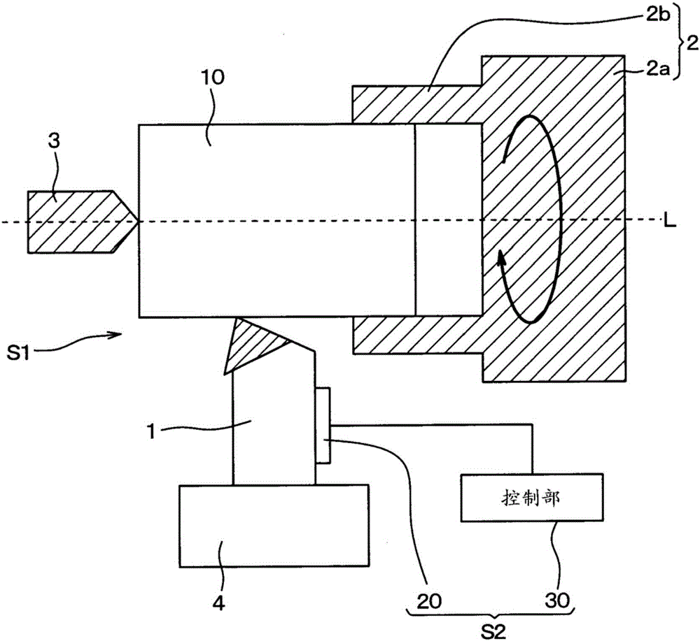
[0031] Such as figure 1 As shown, the cutting device S1 has a cutter part and a pair of first and second clamps 2 and 3 . In the present embodiment, the cutter part 1 is fixed to the support member 4 . In addition, the first jig 2 is configured to have a main body portion 2a and three holding portions 2b protruding in the same direction from the main body portion 2a (in figure 1 Only two are shown in the figure), and the workpiece 10 is sandwiched by the three holding parts 2b. The second jig 3 is arranged on the side of the workpiece 10 opposite to the side held by the first jig 2 so as to fix the workpiece 10 together with the first jig 2 . ...

no. 2 approach

[0090] A second embodiment of the present disclosure will be described. In this embodiment, the heat receiving body is arranged on the opposite side to the thermal buffer body 21a via the first heat flux sensor 20a with respect to the first embodiment, and the rest is the same as that of the first embodiment, so description thereof will be omitted here.

[0091] In this embodiment, if Figure 9 As shown, the state detection sensor 20 is equipped with the heat receiver 25 arrange|positioned on the side opposite to the heat buffer body 21a across the 1st heat flux sensor 20a. That is, the state detection sensor 20 is equipped with the heat receiver 25 arrange|positioned between the cutter part 1 and the 1st heat flux sensor 20a. The heat receiving body 25 is formed of a member having a predetermined heat capacity (thermal resistance) in the same manner as the heat buffer body 21a and the radiator 22, and has a flat plate shape, and is made of metal such as Cu and Al, resin, or ...

no. 3 approach

[0095] A third embodiment of the present disclosure will be described. Compared with the first embodiment, this embodiment further includes a plurality of heat flux sensors and thermal buffers, and the rest is the same as that of the first embodiment, so description thereof will be omitted here.

[0096] In this embodiment, if Figure 10 As shown, for the state detection sensor 20, in addition to the first and second heat flux sensors 20a, 20b and the thermal buffer 21a, the third and fourth heat flux sensors 20c, 20d and the thermal buffer 21b are also provided. , 21c. Moreover, the state detection sensor 20 is arranged from the side of the cutter part 1 according to the first heat flux sensor 20a, the thermal buffer 21a, the second heat flux sensor 20b, the thermal buffer 21b, the third heat flux sensor 20c, and the thermal buffer 21c. , the fourth heat flux sensor 20d and the radiator 22 are arranged in sequence.

[0097] The third and fourth heat flux sensors 20c and 20...


PUM

PropertyMeasurementUnit
melting pointaaaaaaaaaa

Abstract

A state detection sensor is provided with a first heat flux sensor (20a) that outputs a first sensor signal associated with a passing heat flux, a second heat flux sensor (20b) that outputs a second sensor signal associated with a passing heat flux, a thermal buffer element (21a) having a prescribed heat capacity, and a heat radiator element (22) having a prescribed heat capacity. The first heat flux sensor (20a), the thermal buffer element (21a), the second heat flux sensor (20b), and the heat radiator element (22) are arranged in that order from a target object (1, 403, 504, 507). The design is such that the first sensor signal associated with heat flux between the target object and the thermal buffer element (21a) is outputted by the first heat flux sensor (20a), and the second sensor signal associated with heat flux between the thermal buffer element (21a) and the heat radiator element (22) is outputted by the second heat flux sensor (20b).

Description

[0001] This disclosure is based on Japanese Patent Application No. 2014-213680 filed on October 20, 2014, and the content is disclosed in this specification through this disclosure. technical field [0002] The present disclosure relates to a state detection sensor that detects the state of an object. Background technique [0003] Conventionally, there has been proposed an abnormality determination device that uses a state detection sensor that detects the state of an object to determine abnormal heating of the object based on a sensor signal output from the state detection sensor (for example, refer to Patent Document 1). That is, the abnormality determination device includes a state detection sensor including a temperature sensor for detecting the temperature of the upper surface of the object and a temperature sensor for detecting the temperature of the lower surface of the object. In addition, the object is a structure that generates convection due to heat generation. F...

Claims


Application Information

Patent Timeline
Patent Type & Authority Applications(China)
IPC IPC(8): G01K17/00G01K7/02
CPCG01K3/08G01K17/20G01K7/02G01K17/00G01K3/14
Inventor 乡古伦央坂井田敦资谷口敏尚冈本圭司白石芳彦
Owner DENSO CORP
Why Eureka
Try Eureka