Liquid crystal display device

A technology of liquid crystal display device and liquid crystal display panel, which is applied in the direction of identification device, static indicator, optics, etc., and can solve the problems of lower detection accuracy of external light, difficult screen brightness adjustment, lower detection accuracy, etc.

Inactive Publication Date: 2009-12-23
SHARP KK
View PDF8 Cites 0 Cited by
  • Summary
  • Abstract
  • Description
  • Claims
  • Application Information

AI Technical Summary

Problems solved by technology

In this case, the stray light 112 interferes with the optical sensor 104, reducing the detection accuracy of external light by the optical sensor 104.
In addition, as a result, it is difficult to properly adjust the brightness of the screen in the liquid crystal display device.
[0016] An object of the present invention is to provide a liquid crystal display device that solves the above-mentioned problems and can suppress a decrease in detection accuracy when detecting external light.

Method used


Image

  • Liquid crystal display device
  • Liquid crystal display device
  • Liquid crystal display device

Examples


Embodiment Construction

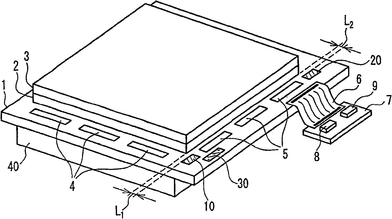
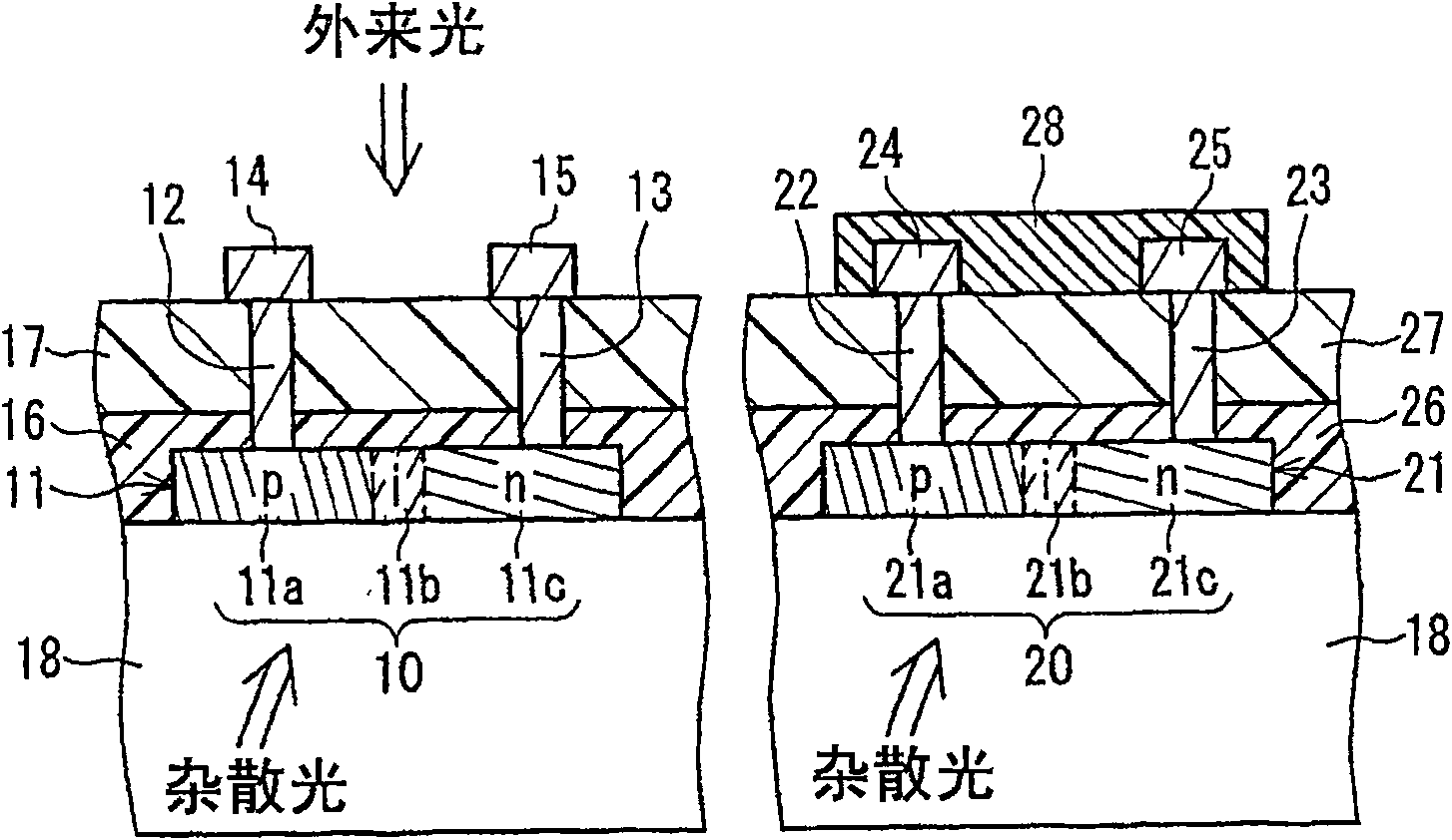
[0024] The liquid crystal display device of the present invention has a liquid crystal display panel formed by sandwiching a liquid crystal layer between an active matrix substrate and a counter substrate, and a backlight for illuminating the liquid crystal display panel from the side of the active matrix substrate, wherein the aforementioned The active matrix substrate has a first light sensor and a second light sensor in the peripheral area of ​​the display area of ​​the substrate surface on the liquid crystal layer side, and the first light sensor is formed in such a way that the light outside the liquid crystal display device The light transmitted inside the active matrix substrate enters, and the second photosensor is formed so that the light transmitted inside the active matrix substrate enters and blocks the external light.

[0025] In the above-mentioned liquid crystal display device of the present invention, it is preferable that the first photosensor and the second ph...


PUM


Abstract

In a liquid crystal display device having a liquid crystal display panel formed by sandwiching a liquid crystal layer between an active matrix substrate and a counter substrate, and a backlight for illuminating the liquid crystal display panel from the side of the active matrix substrate, the active matrix substrate In the peripheral area on the glass substrate 18, the first photosensor 10 and the second photosensor 20 are arranged. The first photosensor 10 is formed such that light outside the liquid crystal display device and light propagating inside the active matrix substrate enters. The second photosensor 20 is formed such that only light propagating inside the active matrix substrate enters. In addition, light from the outside is shielded from the second photosensor 20 . For example, a light shielding film 28 is formed on the upper surface of the second photosensor 20 .

Description

technical field [0001] The present invention relates to a liquid crystal display device having a photosensor. Background technique [0002] In recent years, as a liquid crystal display device, a liquid crystal display device having a so-called environmental sensor (hereinafter referred to as "external sensor") for detecting the intensity of ambient light (hereinafter referred to as "external light") is known (for example, see Patent Document 1 and Patent Document 2). In such a liquid crystal display device, the intensity of light from the backlight is adjusted based on the detected intensity of external light. [0003] Specifically, in the case of a transmissive liquid crystal display device, the light intensity of the backlight is increased in a bright environment such as outdoors, and the light intensity of the backlight is decreased at night or in a relatively dark environment such as indoors. Therefore, according to the liquid crystal display device having the external...

Claims


Application Information

Patent Timeline
Patent Type & Authority Patents(China)
IPC IPC(8): G02F1/133G02F1/13357G02F1/1345G09F9/00G09G3/20G09G3/34G09G3/36H01L31/10G02F1/1335
CPCG09G2360/145G02F1/13306G09G3/3406G02F2001/13312G09G2360/144G02F1/13312
Inventor 加藤浩巳和泉良弘前田和宏
Owner SHARP KK
Why Eureka
Try Eureka