Unlock instant, AI-driven research and patent intelligence for your innovation.
angular velocity sensor
What is Al technical title?
Al technical title is built by PatSnap Al team. It summarizes the technical point description of the patent document.
A technology of angular velocity sensor and driver sheet, which is applied to instruments, gyro effect for velocity measurement, velocity/acceleration/shock measurement and other directions, which can solve problems such as decreased detection accuracy
Active Publication Date: 2019-05-17
DENSO CORP
View PDF7 Cites 0 Cited by
Summary
Abstract
Description
Claims
Application Information
AI Technical Summary
This helps you quickly interpret patents by identifying the three key elements:
Problems solved by technology
Method used
Benefits of technology
Problems solved by technology
In addition, if the first and second drive pieces are displaced in the normal direction, the moment caused by the displacement is transmitted to the detection piece, resulting in a decrease in detection accuracy.
Method used
Image
Click on the blue label to locate the original text in one second.
Reading with bidirectional positioning of images and text.
Examples
no. 1 Embodiment approach
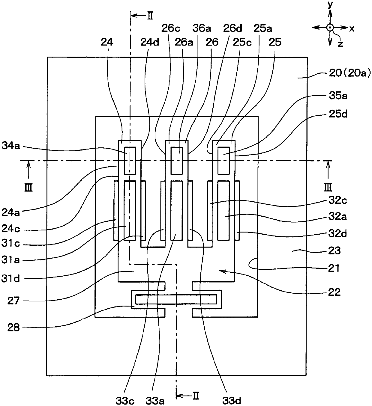
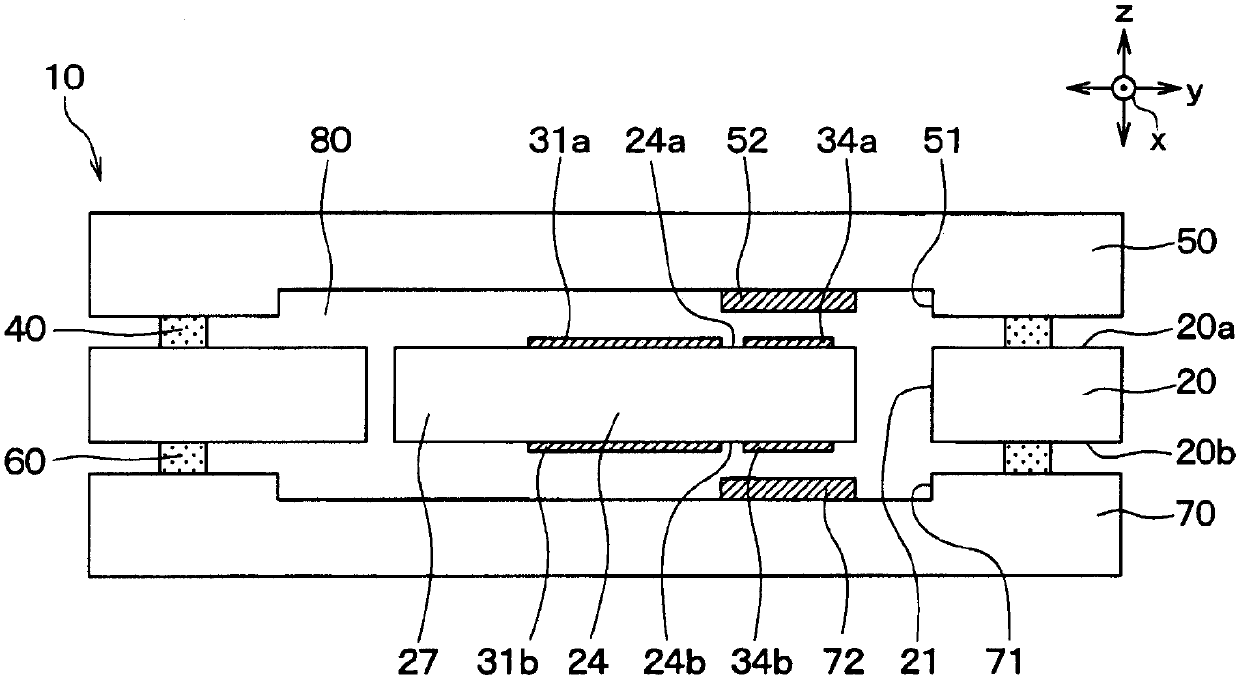
[0034] A first embodiment of the present application will be described with reference to the drawings. The angular velocity sensor of this embodiment has a sensor unit and a circuit unit, and first, the configuration of the sensor unit will be described.
[0035] Such as Figure 1 ~ Figure 3 As shown, the sensor unit 10 includes a first substrate 20 having one surface 20 a and the other surface 20 b opposite to the one surface 20 a. One surface 20a is also referred to as a first surface, and the other surface 20b is also referred to as a second surface. The first substrate 20 is made of crystal, PZT (lead zirconate titanate), etc. as a piezoelectric material. Further, the first substrate 20 is subjected to well-known microfabrication to form the groove portion 21 , and the vibrating body 22 and the outer peripheral portion 23 are separated and formed by the groove portion 21 .
[0036] The vibrator 22 is configured such that the first and second drive pieces 24 and 25 and t...
no. 2 Embodiment approach
[0082] A second embodiment of the present application will be described. This embodiment does not include the control electrodes 34 b , 35 b , and 36 b and the lower electrodes 72 to 74 compared to the first embodiment, and the rest are the same as those of the first embodiment, so description thereof will be omitted here.
[0083] In this embodiment, if Figure 8 As shown, the control electrodes 34 b , 35 b , and 36 b are not formed on the first and second drive chips 24 , 25 and the detection chip 26 . In addition, the lower electrodes 72 to 74 are not formed on the third substrate 70 .
[0084] and, if Figure 9 As shown, the circuit unit 90 does not include the second control circuits 101a to 101c, and the ground potential as a reference potential is input to the C-V conversion circuits 97a to 97c.
[0085] Next, the operation of such an angular velocity sensor will be described by taking the first driving piece 24 as an example.
PUM
Abstract
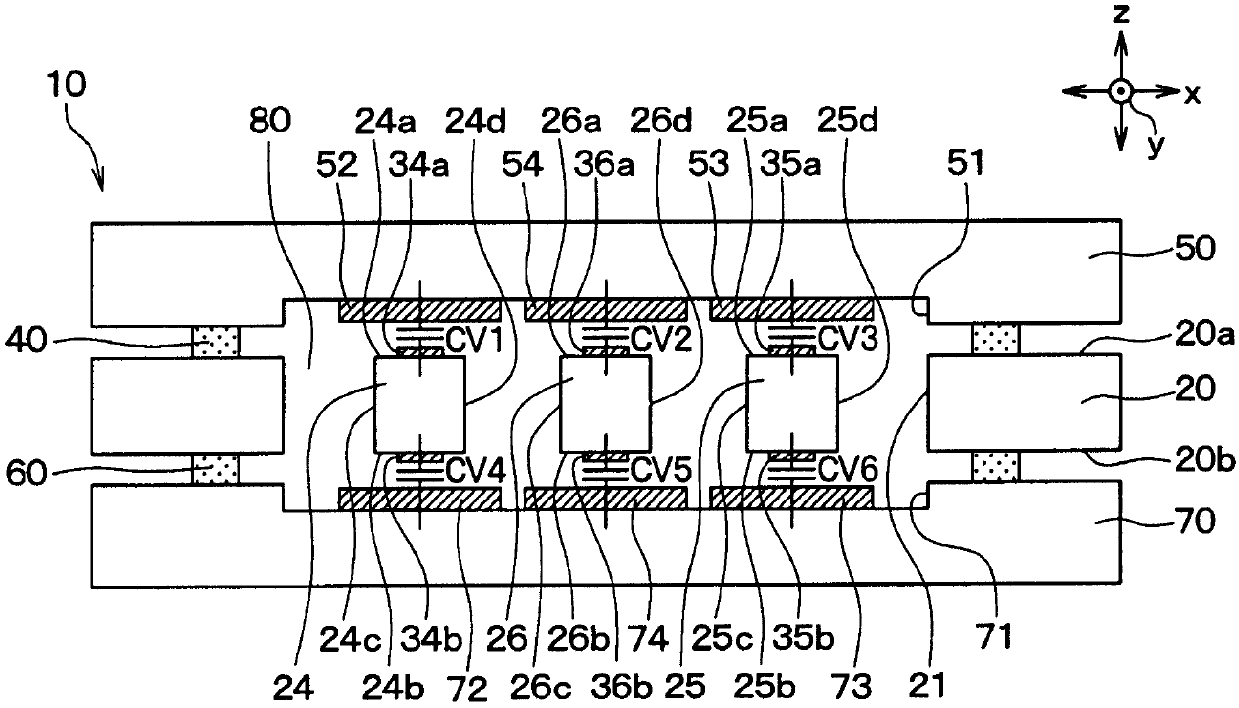
A angular speed sensor with: 1st substrate (20) of the first side (20B) on the opposite side of the first side (20B), formed on the 1st substrate and has the 1st substrate.The vibration bodies (22) of the driving film (24, 25, 114) on the plane direction (24, 25, 114), the 2nd substrate (50) on the 1st side of the 1st side of the 1st, and the side of the 2nd base side sidePart 1 of the parts (34A, 35A) of the part of the part, the part that is compared with the variable -bit area formed in the 2nd substrate, andCV2) The 1st Drive Film Auxiliary Electric (52, 53), and the 1st Drive Cable Control Circle (100A, 100B) of the 1st Drive Film Auxiliary Electrical Voltage (100A, 100B)The capacitor composed of the control electrode and the 1st driver film auxiliary electrode, adjust the voltage applied to the 1st drive film auxiliary electrode, so that the distance between the 1st drive film control electrode and the 1st drive film auxiliary electrode is fixed.
Description
[0001] Cross References to Related Applications [0002] This application is based on Japanese application number 2014-089319 for which it applied on April 23, 2014, and uses the description content here. technical field [0003] The present application relates to an angular velocity sensor with a vibrating body. Background technique [0004] Conventionally, as this kind of angular velocity sensor, an angular velocity sensor having a vibrating body in which first and second drive pieces and detection pieces are fixed to a base has been proposed (for example, refer to Patent Document 1). [0005] Specifically, the vibrating body of this angular velocity sensor is formed by etching a substrate made of a piezoelectric material, and is a so-called three-legged tuning fork in which the first and second drive pieces and detection pieces protrude in the same direction from the base. type. [0006] In addition, the detection piece is arranged between the first and second driving p...
Claims
Application Information
Patent Timeline
Application Date:The date an application was filed.
Publication Date:The date a patent or application was officially published.
First Publication Date:The earliest publication date of a patent with the same application number.
Issue Date:Publication date of the patent grant document.
PCT Entry Date:The Entry date of PCT National Phase.
Estimated Expiry Date:The statutory expiry date of a patent right according to the Patent Law, and it is the longest term of protection that the patent right can achieve without the termination of the patent right due to other reasons(Term extension factor has been taken into account ).
Invalid Date:Actual expiry date is based on effective date or publication date of legal transaction data of invalid patent.

