Backlight device and liquid crystal display device provided with same

A backlight and light source technology, applied in the field of backlight devices, can solve problems such as high power consumption, complicated drive circuits, and high cost

Inactive Publication Date: 2017-02-22
SHARP KK
View PDF12 Cites 4 Cited by
  • Summary
  • Abstract
  • Description
  • Claims
  • Application Information

AI Technical Summary

Problems solved by technology

[0005] according to Figure 28 composition shown, with Figure 26 the composition shown, Figure 27 Compared with the configuration shown, the drive circuit becomes more complicated, resulting in high cost and high power consumption

Method used


Image

  • Backlight device and liquid crystal display device provided with same
  • Backlight device and liquid crystal display device provided with same
  • Backlight device and liquid crystal display device provided with same

Examples


no. 1 Embodiment approach >

[0128]

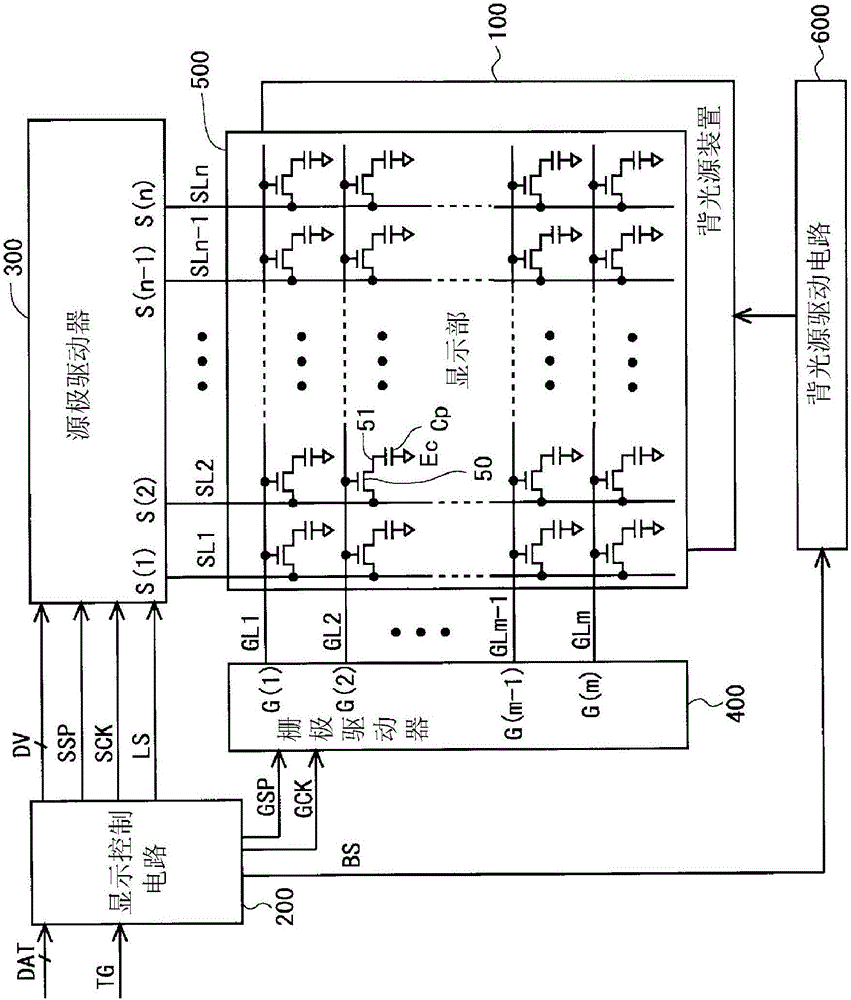
[0129] figure 2 It is a block diagram showing the overall configuration of a liquid crystal display device including the backlight unit according to the first embodiment of the present invention. The liquid crystal display device includes: a backlight device 100, a display control circuit 200, a source driver (video signal line driving circuit) 300, a gate driver (scanning signal line driving circuit) 400, a display unit 500, and a backlight driving circuit 600.

[0130] In the display unit 500, it includes: a plurality (n) of source bus lines (video signal lines) SL1˜SLn, a plurality (m) of gate bus lines (scanning signal lines) GL1˜GLm, and Intersections of the bus lines SL1 to SLn and the plurality of gate bus lines GL1 to GLm respectively correspond to a plurality (n×m) of pixel formation portions provided. These pixel forming portions are arranged in a matrix to form a pixel array. Each pixel forming portion includes: a thin film transistor (TFT) 50 as a swi...

no. 2 Embodiment approach >

[0158]

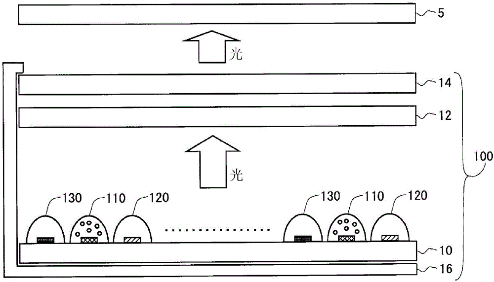
[0159] Overall composition (refer to figure 2 ) and the composition of the backlight unit 100 ( image 3 ) is the same as that of the above-mentioned first embodiment, and therefore description thereof will be omitted. However, about image 3 The configuration of the LED module mounted on the LED substrate 10 is different between the above-mentioned first embodiment and this embodiment. Figure 9 It is a figure which shows the structure of the LED module mounted on the LED board|substrate 10 in this embodiment. In this embodiment, the LED module includes: a magenta light emitter 110 in which a blue LED element 112 is covered with a red phosphor 114 , a green light emitter 120 including a green LED element 122 , and a blue light emitter including a blue LED element 142 . illuminant 140 . That is, the structure of the LED module of this embodiment is Figure 29 The configuration of the blue light emitting body 140 including the blue LED element 142 is added to t...

no. 3 Embodiment approach >

[0167]

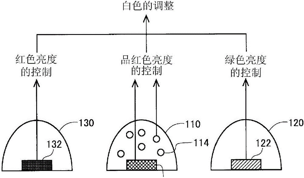
[0168] Overall composition (refer to figure 2 ) and the composition of the backlight unit 100 ( image 3 ) is the same as that of the above-mentioned first embodiment, and therefore description thereof will be omitted. However, about image 3 The configuration of the LED module mounted on the LED substrate 10 is different between the above-mentioned first embodiment and this embodiment. Figure 12 It is a figure which shows the structure of the LED module mounted on the LED board|substrate 10 in this embodiment. In this embodiment, the LED module includes: a magenta light emitter 110 in which a blue LED element 112 is covered with a red phosphor 114 , a green light emitter 120 including a green LED element 122 , and a red light emitter including a red LED element 132 130 and a blue light emitter 140 comprising a blue LED element 142 . That is, the structure of the LED module of this embodiment is Figure 29 The structure of the red light emitter 130 including ...


PUM


Abstract

The objective of the present invention is to provide a backlight device for a liquid crystal display device with which it is possible to suitably calibrate the white point and with which it is possible to realize a wide color gamut. An LED module that is a light source of the backlight device is configured using a magenta light-emitting body (110) having a structure that covers a blue LED element (112) with a red fluorescent body (114), a green light-emitting body (120) comprising a green LED element (122), and a red light-emitting body (130) comprising a red LED element (132). A backlight-driving circuit independently controls the luminance of light generated from the magenta light-emitting body (110), the luminance of light generated from the green light-emitting body (120), and the luminance of light generated from the red light-emitting body (130).

Description

technical field [0001] The present invention relates to a backlight device, and more specifically, to a backlight device for a liquid crystal display device in which LEDs (light emitting diodes) are used as light sources. Background technique [0002] In recent years, digital devices have become significantly more functional and high-performance, and demands for higher quality of various images have increased. Therefore, in the fields of display devices, printing devices, imaging devices, etc., the range of color reproduction (also referred to as "color gamut") has been expanded compared to conventional ones. With regard to liquid crystal display devices such as liquid crystal televisions, attempts have been made to expand the color reproduction range by, for example, improving backlight devices and color filters. [0003] However, in a liquid crystal display device, color display is performed by additive color mixing of three primary colors. Therefore, in a transmissive l...

Claims


Application Information

Patent Timeline
Patent Type & Authority Applications(China)
IPC IPC(8): G02F1/133G02F1/13357G09G3/34G09G3/36H05B44/00
CPCG09G3/36G09G3/3406G09G3/3413G09G2320/0666G02F1/133603G02F1/133609G02F1/133621H05B45/20G02F1/133614
Inventor 田中敦幸井上尚人
Owner SHARP KK
Why Eureka
Try Eureka