Control rod steering reset structure of electric balance car

A technology of electric balance car and reset structure, which is applied in the direction of steering mechanism, electric scooter, motor vehicle, etc. It can solve the problems of difficult installation, poor reset effect, complex structure of reset mechanism, etc., and achieves simple and reasonable structure, easy installation and disassembly, Good reset effect

Active Publication Date: 2017-03-01
HANGZHOU SUKONG SOFTWARE CO LTD
View PDF12 Cites 2 Cited by
  • Summary
  • Abstract
  • Description
  • Claims
  • Application Information

AI Technical Summary

Problems solved by technology

[0004] The above-mentioned scheme alleviates to a certain extent the problem that the existing joystick reset structure is difficult to accurately reset the joystick to the middle position, but because the reset mechanism structure in this scheme is too complicated, it is relatively difficult in actual installation, and there is still: reset Poor effect and lack of stability

Method used


Image

  • Control rod steering reset structure of electric balance car
  • Control rod steering reset structure of electric balance car
  • Control rod steering reset structure of electric balance car

Examples


Embodiment 1

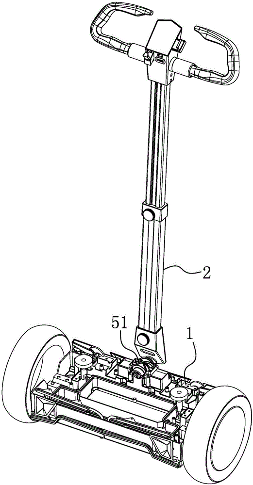
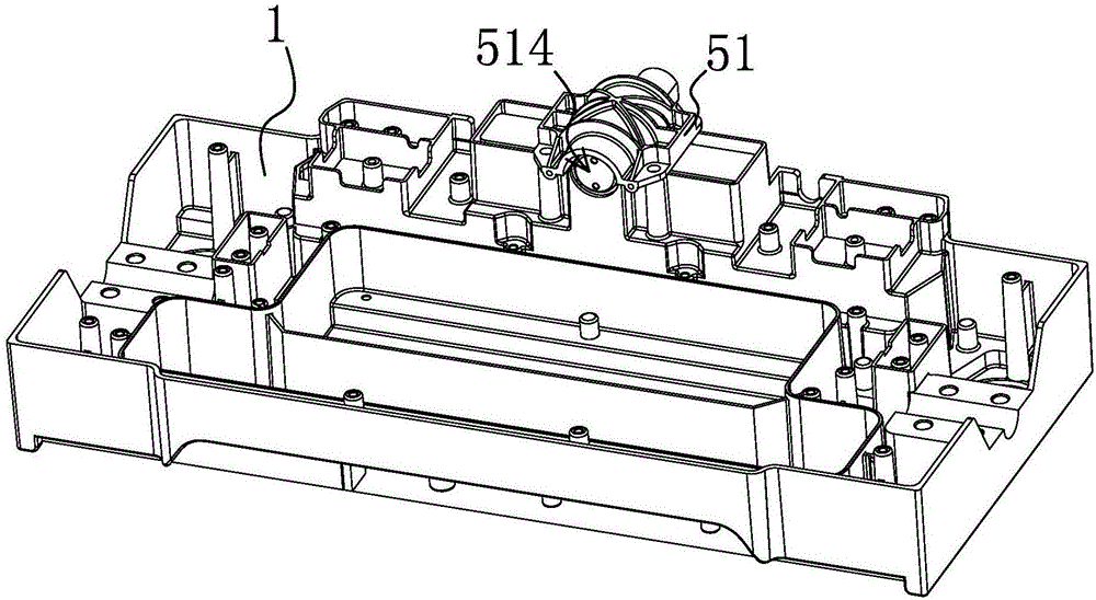
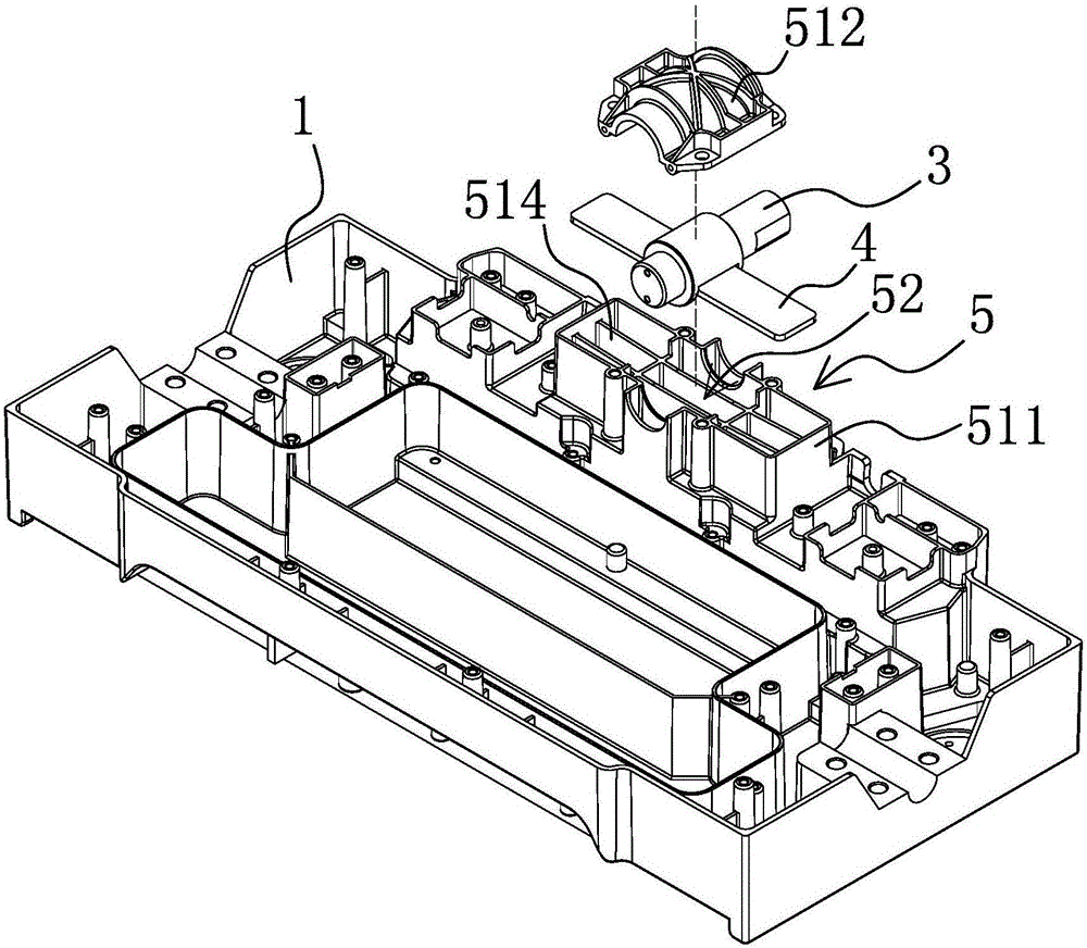
[0027] Such as Figure 1-3 As shown, the control lever steering reset structure of the electric balance vehicle is arranged between the pedal seat 1 and the control lever 2 of the electric balance vehicle, including a rotating shaft arranged at the lower part of the control lever 2 and can rotate as the control lever 2 swings 3. The rotating shaft 3 is rotatably connected to the pedal seat 1 and the control rod 2 remains in the center position when the control rod 2 is not subjected to external force. The pedal seat 1 is equipped with a control rod 2 that drives the rotating shaft 3 to rotate in any direction when the control rod 2 swings. When it is driven by the rotating shaft 3 and deformed so that the rotating shaft 3 has an elastic sheet 4 with a tendency to rotate in the opposite direction, the end of the elastic sheet 4 is located outside the rotating shaft 3, that is, the elastic sheet 4 produces a deformation force opposite to the rotation direction of the rotating sha...

Embodiment 2

[0033] Such as Figure 7 As shown, the structure, principle and implementation steps of this embodiment are similar to those of Embodiment 1, the difference lies in that at least one elastic sheet 4 is provided on both sides of the rotating shaft 3 here, and one end of the elastic sheet 4 is fixedly connected with the rotating shaft 3 , and the other end extends outward, that is, the elastic sheet 4 here has multiple pieces, which are respectively arranged on both sides of the rotating shaft 3 .


PUM


Abstract

The invention relates to a control rod steering reset structure of an electric balance car. The technical problem that control rod steering reset of an existing electric balance car is low in accuracy is solved. The structure is arranged between a pedal seat and a control rod of the electric balance car, and comprises a rotary shaft which is arranged on the lower portion of the control rod and can rotate along with swing of the control rod, the rotary shaft and the pedal seat are rotationally connected, and when the control rod does not bear exogenic action, the control rod is kept in the middle. An elastic sheet is arranged in the pedal seat, when the control rod swings and drives the rotary shaft to rotate in any direction accordingly, the elastic sheet can be driven by the rotary shaft to deform, and therefore the rotary shaft has a reverse rotating trend, and the end of the elastic sheet is located on the outer side of the rotary shaft. The control rod steering reset structure has the advantages that the control rod steering reset structure is simple and reasonable, good in stability and good in reset effect, capable of ensuring that the control rod can be reset to the middle position accurately in time and convenient to mount and demount; the elastic sheet is made from a manganese steel sheet, and enough elastic force can be provided.

Description

technical field [0001] The invention belongs to the technical field of electric vehicle equipment, and in particular relates to a control lever steering reset structure of an electric balance vehicle. Background technique [0002] Electric balance car, also known as somatosensory car, thinking car, camera car and so on. There are mainly two types of single wheel and double wheel on the market. Its operating principle is mainly based on a basic principle called "dynamic stability". The gyroscope and acceleration sensor inside the car body are used to detect changes in the body's attitude, and the servo control system is used to accurately drive the motor. Adjust accordingly to keep the system in balance. Common electric balance vehicles are mainly divided into electric balance vehicles controlled by joysticks or electric balance torsion vehicles or single-wheel electric balance vehicles that are articulated by two pedal seats. Among them, joystick-type electric balance vehi...

Claims


Application Information

Patent Timeline
IPC IPC(8): B62K21/10
CPCB62K21/10B62K2202/00B62K2204/00
Inventor 朱筱凯
Owner HANGZHOU SUKONG SOFTWARE CO LTD
Why Eureka
Try Eureka