fluid flow valve

A flow-through valve and fluid technology, applied in the direction of charging system, machine/engine, engine control, etc., can solve the feasibility of restricting the use of actuators, etc.

Active Publication Date: 2020-09-22
VALEO SYST DE CONTROLE MOTEUR
View PDF6 Cites 0 Cited by
  • Summary
  • Abstract
  • Description
  • Claims
  • Application Information

AI Technical Summary

Problems solved by technology

This operation only possible in one direction limits the feasibility of using the actuator

Method used


Image

  • fluid flow valve
  • fluid flow valve
  • fluid flow valve

Examples


Embodiment Construction

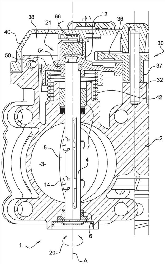
[0027] like figure 1 As shown, the invention relates to a fluid communication valve 1, in particular for use in motor vehicles. It is here a valve for regulating the intake air flow of a heat engine, in particular a metering valve for a diesel engine.

[0028] This valve is a valve known to those skilled in the art, for example as described in patent application FR2992046.

[0029] In particular, the valve comprises a body 2 inside which a conduit 3 for fluid communication is arranged. Here, the main body 2 is intended to be mounted on the intake line of the engine by means of a connection so that the part of the gas flowing into this branch passes through the line and is directed towards the engine to participate in combustion. Connections and intake lines are known per se and are not shown.

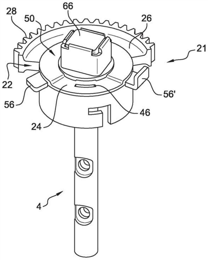
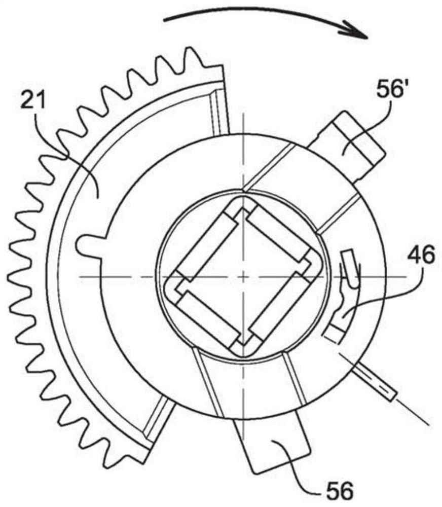
[0030] In the body 2 of the valve 1 is received a control shaft 4 which is free to rotate together with a valve 5 which is solidified as indicated by an arrow 20 which rotates about ...


PUM


Abstract

The invention relates to a fluid flow valve comprising a body (2) having a pipe (3) through which the fluid flows, a flap (5) sealing the pipe (3), an actuator (4) of the flap (5), the actuator being freely rotatable and comprising a return spring (42), a member (21) for rotating the actuator (4), and a means (423) for radially stopping a first end (421) of the spring (42), characterised in that the valve includes at least one means for catching (46) a second end (422) of the spring (42), the catching means (46) being configured such as to receive the second end (422) of the spring in a clockwise or counter-clockwise direction of rotation of the rotating member (21).

Description

technical field [0001] The present invention relates to a fluid communication valve, and more particularly, the present invention relates to a fluid communication valve for a motor vehicle. Background technique [0002] The valve is more particularly intended for use as an intake metering valve of an internal combustion engine, whether gasoline or diesel. The valve is also used as an exhaust gas recirculation valve or EGR (that is, the English term "Exhaust GazRecirculation") valve. Other applications of the valve according to the invention are also possible without going beyond the scope of the invention. [0003] Actuators are known which operate according to reversible kinematics (for example actuators for fluid communication valves). These actuators or control shafts use torsion springs connected to sector gears or gears as elements for returning to their equilibrium positions. The spring consists of a fixed part that stops in a slot or on an un plot and a movable par...

Claims


Application Information

Patent Timeline
Patent Type & Authority Patents(China)
IPC IPC(8): F02D9/10F02M26/70F02M26/72
CPCF02D9/1035F02D9/1065F02D9/107F02M26/70F02M26/72
Inventor M.桑切斯G.达沃尔特
Owner VALEO SYST DE CONTROLE MOTEUR
Why Eureka
Try Eureka