
Low cost MR safe touchscreen monitor

A technology of touch screen and display, applied in magnetic resonance measurement, measurement using nuclear magnetic resonance imaging system, instruments, etc., can solve the problems of difficult to produce small equipment, expensive touch screen display, etc., to achieve easy removal, reduce electromagnetic interference emission, and easy manufacturing Effect

Active Publication Date: 2019-06-04
KONINKLJIJKE PHILIPS NV
View PDF5 Cites 0 Cited by
  • Summary
  • Abstract
  • Description
  • Claims
  • Application Information

AI Technical Summary

Problems solved by technology

As a result, current touchscreen displays are small devices that are expensive and difficult to produce

Method used


Image

  • Low cost MR safe touchscreen monitor
  • Low cost MR safe touchscreen monitor
  • Low cost MR safe touchscreen monitor

Examples


Embodiment Construction

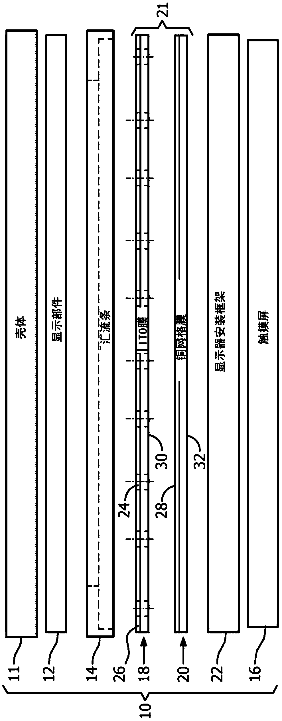
[0031] refer to Figures 1A-1B A magnetic resonance (MR) safe touch screen display 10 includes a display component 12 , bus bars 14 and a touch screen 16 component. Bus bar 14 is conductively coupled to low frequency shield 18 and high frequency shield 20 , and contacts display mounting frame 22 of touch screen 16 . In a variant embodiment, the housing 11 of the display part 12 is in electrical contact with the bus bars 14 to form a Faraday cage, as discussed below.

[0032] Touch screen 16 may be implemented as a resistive touch screen in which two flexible sheets coated with resistive material are separated via an air gap or a physical separation feature. When pressure from the user is on the outer sheet, a circuit is formed using the inner sheet, which is then processed to determine the corresponding location on the display 12 that the user wants to touch. Capacitive displays use a different mechanism and require the use of specialized gloves, no gloves, or a special pen....


PUM


Abstract

A magnetic resonance (MR) safety touch screen display (10), including: a touch screen (16) and a film (30, 32), the film having a high frequency shielding layer (20, 28) and a low frequency shielding layer (18, 26) . Bus bars (14) conductively couple the low frequency shielding layers (18, 26) to the high frequency shielding layers (18, 26) at the perimeter of the faces of the membranes (30, 32) and around the edges of the membranes (30, 32). Frequency shielding layer (20, 28). Membranes (30, 32) are adjacent to the back of the touch screen (16). Busbars (14) facilitate the connection of the touch screen (16) and layers (18, 20) to the display (12) to form a Faraday cage around the display components contained within the display housing (11).

Description

technical field [0001] The following generally relates to accessories compatible with magnetic resonance (MR) imaging. It is particularly suitable for use in conjunction with, and will be described with particular reference to, a shielded display operable in an MR operating environment. It will however be understood that it also finds application in other use cases and is not necessarily limited to the aforementioned applications. Background technique [0002] Magnetic resonance (MR) techniques require ever-increasing diagnostic detail and enhanced monitoring information on patient monitoring equipment. MR monitoring is becoming more common and more critical in response to patient needs. This increased need for patient information combined with improvements in display and touch panel technology has moved the industry towards larger displays and improved interfaces. [0003] Monitors and other equipment used in the MR environment must be handled by a gloved clinician. In ...

Claims


Application Information

Patent Timeline
Patent Type & Authority Patents(China)
IPC IPC(8): G01R33/28G06F3/045G01R33/54
CPCG01R33/543G06F3/045G06F2203/04107G01R33/283G06F2203/04103G01R33/28
Inventor F·P·奥尼尔R·P·孔西利奥D·A·福雷尔
Owner KONINKLJIJKE PHILIPS NV
Learn More