
Percussion releasing device used for axial powder actuated tool

A technology of releasing device and nailer, which is applied in nailing tools, manufacturing tools and other directions, can solve the problems of poor processing accuracy, high manufacturing cost and high roughness, and achieve the effect of reducing the difficulty of processing and assembly and reducing the manufacturing cost.

Inactive Publication Date: 2017-03-08
YIBIN NANXI KECHENG ELECTROMECHANICAL FACTORY
View PDF11 Cites 2 Cited by
  • Summary
  • Abstract
  • Description
  • Claims
  • Application Information

AI Technical Summary

Problems solved by technology

[0005] 1. When working on the top surface, such as when working on the ceiling, the construction personnel must use ladders or scaffolding so that the hands can reach the trigger position of the nail shooter before construction. Obviously, such work efficiency is extremely low, and construction personnel The labor intensity is very high, and there will be safety hazards
[0006] 2. When working on the ground, the construction personnel must also bend over to operate. Working in this way for a long time will also cause chronic damage to the construction personnel's body
[0007] 3. When working on the side, sometimes the wall surface that needs to be constructed, due to terrain restrictions or the existence of obstacles, also prevents construction personnel from approaching, and there is also a situation where construction is difficult
[0017] The manufacturing and assembly process is complex, especially the oblique key (trigger key) structure in the main sleeve, which poses great difficulties in processing: the inner hole diameter of the main sleeve is small, and can only be cut into the firing key by wire cutting. The processing efficiency is low, and the manufacturing cost is high. In addition, the processing accuracy is poor and the roughness is high. This processing form directly affects the quality index of the entire equipment; there is also a gap in the accuracy of circumferential positioning (key and groove fit) in the entire assembly method. Problem; In order to solve this problem, the inventor also applied for a patent: the block-type axial nail shooter (application number: 201610383377.9), which processed the firing key as an external part and assembled it on the main sleeve, but did not essentially overcome the disadvantages

Method used


Image

  • Percussion releasing device used for axial powder actuated tool
  • Percussion releasing device used for axial powder actuated tool
  • Percussion releasing device used for axial powder actuated tool

Examples


Embodiment

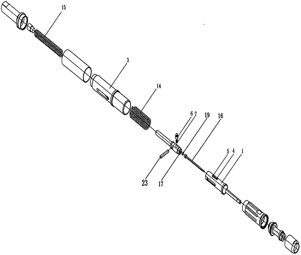
[0041] The front end of the nail shooter is pressed against the substrate and compressed, and the firing sleeve 1 moves backward in the main sleeve 3 . At this time, the brake pin 6 is located in the through hole 5 and moves accordingly, and its detail 10 drives the hammer 2 to move backward at the same time (such as Figure 6 shown). During the aforementioned movement, the firing spring 15 is compressed by the hammer 2 .

[0042] When moving to the set position, the firing surface 13 inside the main sleeve 3 will contact the top spherical surface of the detail 10, so that the braking pin 6 is compressed downward as a whole.

[0043] When the upper step 11 is located on the inner circumference of the main sleeve 3, the detail 10 is located in the through hole 5 (through groove 4), and because the size of the detail 10 is small, at this time, the restraining effect of the brake pin 6 fails, and the strike The hammer 2 drives the brake pin 6 to move forward rapidly under the a...


PUM


Abstract

The invention relates to an axial percussion type powder actuated tool. The axial percussion type powder actuated tool is characterized in that a shotpin comprises a thick portion on the lower portion, a medium-thin portion located on the thick portion, and a thin portion located on the medium-thin portion, wherein the thin portion and the medium-thin portion form an upper bench, and a lower bench is formed between the thin portion and the thick portion; the width of a through groove is less than the diameter of the medium-thin portion and larger than the diameter of the thin portion; the diameter of a through hole is less than the diameter of the thick portion and larger than the diameter of the medium-thin portion; and a percussion slope is arranged in a main sleeve. The axial percussion type powder actuated tool has the beneficial effects that the structure of the shotpin is changed, the original thin portion of the shotpin is broken up into the thin portion and the medium-thin portion to enable the medium-thin portion to complete a front and back limiting function, and the thin portion only completes the compressed function, so that the shotpin is released with a decreased degree of moving down of the entire shotpin (the thin portion is located in the through groove), the direct effect is that a taper key structure can be changed into an annual slope structure, the difficulty of machining and assembly is reduced, manufacture cost is reduced, and in addition, a circumferential positioning design and a percussion groove design behind the through hole can be omitted.

Description

technical field [0001] The invention discloses a firing release device, which is especially suitable for axial nail shooters. Background technique [0002] The nail shooter is a tool that uses a firing pin to fire a nail bomb, and the thrust generated by the explosion of gunpowder in the nail gun acts as a power to move the ejector rod and drive the nail into the building. [0003] The principle of the firing device of the existing nail shooter is: the firing pin compresses and stores energy through the firing pin spring (the firing pin is limited by the sear at this moment). Then pull the trigger, the rocker of the trigger pushes the sear, and under the thrust of the spring, the firing pin moves forward unconstrained and rapidly, and the front end hits the bottom shell of the nail shooting bomb, causing the nail shooting bomb to explode and generate thrust, which passes through the nail rod Hit the nails to complete the homework task. [0004] In the firing device of the ...

Claims


Application Information

Patent Timeline
Patent Type & Authority Applications(China)
IPC IPC(8): B25C1/14B25C1/18
CPCB25C1/14B25C1/146B25C1/18
Inventor 方福政方鹤周建
Owner YIBIN NANXI KECHENG ELECTROMECHANICAL FACTORY
Learn More