Laser radar system

A technology of laser radar and laser beam, applied in the direction of radio wave measurement system, instrument, etc., to achieve the effect of lower manufacturing cost, high signal-to-noise ratio, and less difficulty in processing and assembly

Pending Publication Date: 2021-06-25
觉芯电子(无锡)有限公司
View PDF0 Cites 1 Cited by
  • Summary
  • Abstract
  • Description
  • Claims
  • Application Information

AI Technical Summary

Problems solved by technology

[0004] However, in the process of implementing the embodiments of the present invention, the inventors found that the common non-coaxial opt

Method used


Image

  • Laser radar system
  • Laser radar system
  • Laser radar system

Examples


Embodiment Construction

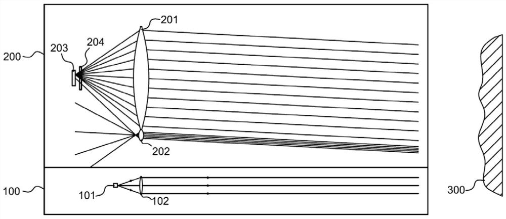
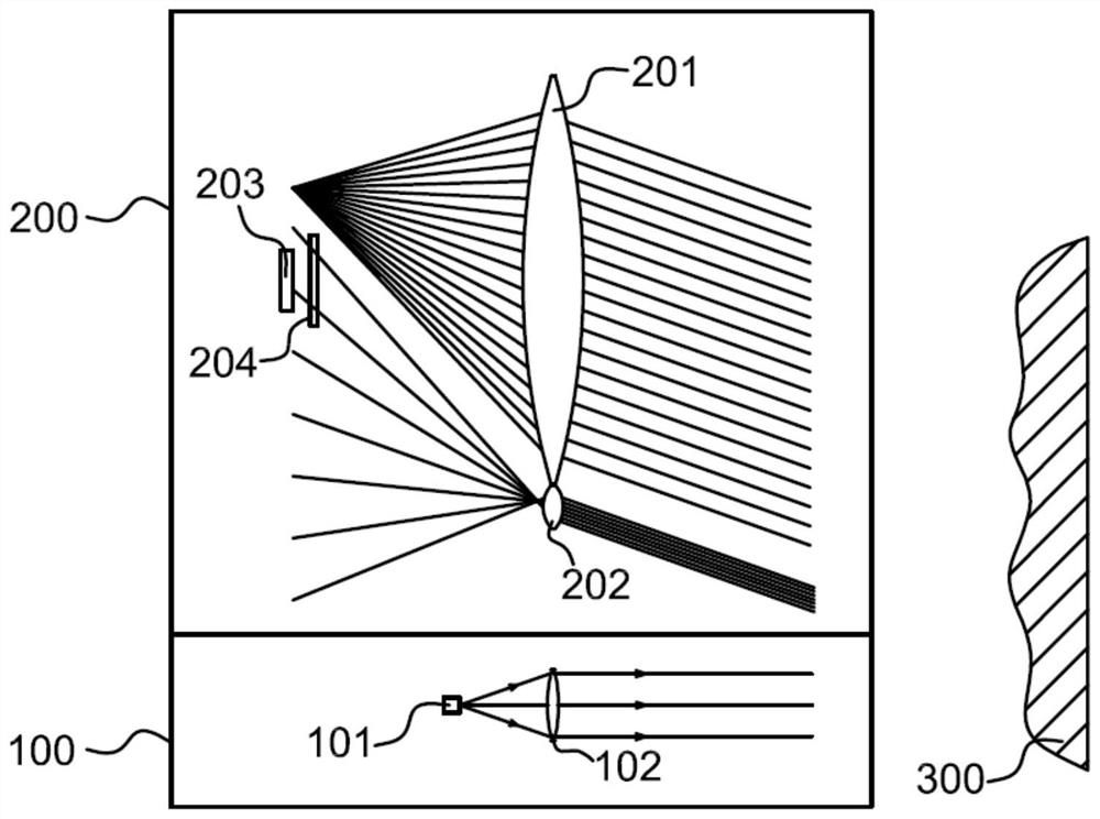
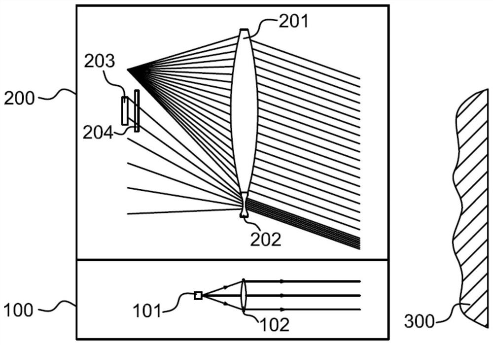
[0035] The following will clearly and completely describe the technical solutions in the embodiments of the present invention with reference to the drawings in the embodiments of the present invention. Apparently, the described embodiments are only some of the embodiments of the present invention, but not all of them. Based on the embodiments of the present invention, all other embodiments obtained by persons of ordinary skill in the art without creative efforts fall within the protection scope of the present invention.

[0036] Reference herein to "one embodiment" or "an embodiment" refers to a particular feature, structure or characteristic that can be included in at least one implementation of the present invention. In the description of the present invention, it should be understood that the orientation or positional relationship indicated by the terms "upper", "lower", "top", "bottom" etc. is based on the orientation or positional relationship shown in the drawings, and i...


PUM


Abstract

A laser radar system provided by the present invention comprises a transmitting module and a receiving module, the transmitting module is used for transmitting a detection laser beam, the receiving module comprises a main receiving lens group, an auxiliary receiving lens group and a detection unit; the main receiving lens group is used for receiving and converging an echo signal of the detection laser beam reflected by a to-be-detected target, so that the signal is received by the detection unit; the auxiliary receiving lens group is used for receiving and diverging an echo signal of the detection laser beam reflected by a to-be-detected target, so that the echo signal can be received by the detection unit; and the detection unit is used for receiving and processing the echo signals transmitted by the main receiving lens group and/or the auxiliary receiving lens group. According to the laser radar system, the main receiving lens group and the auxiliary receiving lens group are arranged for detection, the auxiliary receiving lens group performs effective detection under the short-distance condition, the defect that a non-coaxial laser radar has a short-distance optical detection blind area is overcome, and it can be ensured that the signal-to-noise ratio is high during short-distance detection.

Description

technical field [0001] The invention relates to the technical field of laser radar, in particular to a laser radar system. Background technique [0002] Lidar is an active detection system. Its working principle is to actively transmit laser signals to the target to be measured, and receive the laser signal reflected by the target. By comparing and analyzing the characteristics of the transmitted and received signals, the information of the target to be measured is obtained. . [0003] At present, many lidars are based on the pulse time-of-flight (PTOF) ranging principle to detect the distance and contour of the target. For two-dimensional lidar, according to its transmitting and receiving optical path structure, it can be divided into coaxial optical path and non-coaxial optical path. Because the non-coaxial optical path does not interfere with each other between the transmitting optical path and the receiving optical path, and the structure is relatively simple, it has b...

Claims


Application Information

Patent Timeline
IPC IPC(8): G01S7/481G01S7/48
CPCG01S7/481G01S7/4802
Inventor 马宏
Owner 觉芯电子(无锡)有限公司
Why Eureka
Try Eureka