Puller roller in textured-yarn spinning technology based on real-time lubricating treatment

A technology of space-changing yarn and spinning, which is applied in the field of textile processing, and can solve problems such as the impact on the quality of formed products and the wear and tear of drawing and stretching

Inactive Publication Date: 2017-03-08
南京妙策传媒有限公司
View PDF7 Cites 0 Cited by
  • Summary
  • Abstract
  • Description
  • Claims
  • Application Information

AI Technical Summary

Problems solved by technology

The existing space-changing yarn process needs to process the textile raw materials through rollers. In the process of pulling the textile raw materials through the rollers to form drawn and stretched yarns, it is often difficult for the existing pulling rollers to make the rollers The drawing and stretching wires on the top are kept well lubricated during the drawing process, which makes the drawing and stretching wires prone to wear and tear, so that the quality of the formed products is affected

Method used


Image

  • Puller roller in textured-yarn spinning technology based on real-time lubricating treatment
  • Puller roller in textured-yarn spinning technology based on real-time lubricating treatment

Examples


Embodiment 1

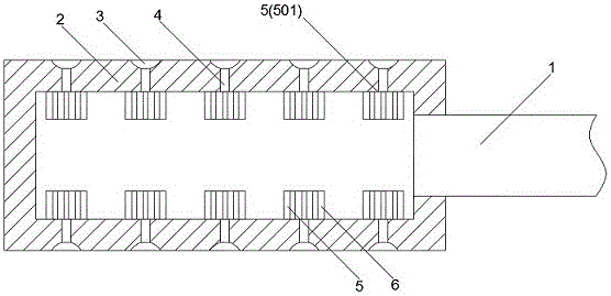
[0015] Such as figure 1 and figure 2 The drawing roller in the shown a kind of air variable yarn spinning process based on real-time lubrication treatment includes a driving shaft body 1, and a roller main body 2 is arranged on the driving shaft body 1, and the roller main body 2 adopts a hollow structure; On the side end surface of the roller main body 2, a plurality of traction grooves 3 extending radially on the roller main body 2 are arranged, and a plurality of traction grooves 3 are evenly distributed in the axial direction of the roller main body 2; Each is provided with a plurality of lubricating oil passages 4 connected to the interior of the roller main body 2. In the roller main body 2, each lubricating oil passage 4 is provided with a lubricating end plate 5 at a corresponding position on the inner wall of the roller main body 2, and the lubricating end plate 5 is sampled. The arc-shaped structure, the end of each lubricating oil passage 4 on the inner wall of th...

Embodiment 2

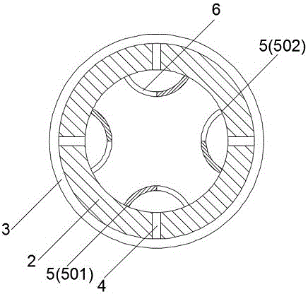
[0019] As an improvement of the present invention, such as figure 2 As shown, the lubricating end plate 5 includes a first end portion 501 and a second end portion 502 distributed sequentially above its extension direction, and the first end portion 501 and the second end portion 502 are both fixed to the bottom of the roller main body 2 On the inner wall, the lubricating end plate 2 extends in an arc between the first end portion 501 and the second end portion 502; 4, and the first end 501 of the lubricating end plate 5 is distributed sequentially in the direction of rotation of the roller main body 2; among the lubricating end plates, an oil inlet hole 6 is provided at the corresponding position of the second end 502 . By adopting the above technical solution, the structure of the lubricating end plate can be set so that the lubricating end plate forms a closed structure relative to the lubricating oil passage, so that the lubricating oil passage inside the lubricating end ...

Embodiment 3

[0022] As an improvement of the present invention, the oil inlet hole 6 extends through the inner wall of the roller body 2 to above the relative position of the lubricating end plate 5 and the axis of the roller body 2 . The above technical solution can effectively improve the efficiency of lubricating oil entering the lubricating end plate, so that there is enough lubricating grease inside the lubricating end plate for lubricating treatment.

[0023] The remaining features and advantages of this embodiment are the same as those of Embodiment 2.


PUM


Abstract

The invention discloses a puller roller in the textured-yarn spinning technology based on real-time lubricating treatment. The puller roller comprises a driving shaft, and a roller body is arranged on the driving shaft; a plurality of pulling grooves extending in the radial direction of the roller body are formed in the side end face of the roller body, and are evenly distributed in the axial direction of the roller body; a plurality of lubricating oil channels communicated inside the roller body are formed in each pulling grooves; in the roller body, lubricating end plates are arranged at the positions, corresponding to the inner wall of the roller body, of all the lubricating oil channels, and are of arc structures, and all the lubricating oil channels and the end of the inner wall of the roller body are located inside the lubricating end plates corresponding to the lubricating oil channels. By means of the puller roller in the textured-yarn spinning technology based on real-time lubricating treatment in the technical scheme, real-time lubricating treatment of the stability of the pulling grooves and pulling stretching silk for pulling treatment in the pulling grooves can be carried out.

Description

technical field [0001] The invention relates to the field of textile processing, in particular to a traction roller in an air variable yarn spinning process based on real-time lubrication treatment. Background technique [0002] The air variable yarn process is one of the new processes for improving the existing fiber materials in the textile field. The existing space-changing yarn process needs to process the textile raw materials through rollers. In the process of pulling the textile raw materials through the rollers to form drawn and stretched yarns, it is often difficult for the existing pulling rollers to make the rollers The drawing and stretching wire on the machine is well lubricated during the drawing process, which makes the drawing and stretching wire prone to wear and tear, so that the quality of its formed products is affected. Contents of the invention [0003] The technical problem to be solved by the present invention is to provide a traction roller in the...

Claims


Application Information

Patent Timeline
Patent Type & Authority Applications(China)
IPC IPC(8): D01D5/16
CPCD01D5/16
Inventor 华明月
Owner 南京妙策传媒有限公司
Why Eureka
Try Eureka