A kind of micro pile horizontal static load test device and method

A technology of horizontal static load and test device, which is applied in the test of foundation structure, construction, foundation structure engineering, etc. It can solve the problems of large horizontal displacement of pile top, low strength of pile body, and small bending stiffness of pile body, etc., and achieve balance Easy adjustment, easy installation and disassembly, and stable device structure

Active Publication Date: 2018-06-08
CHINA UNIV OF GEOSCIENCES (WUHAN)
View PDF6 Cites 2 Cited by
  • Summary
  • Abstract
  • Description
  • Claims
  • Application Information

AI Technical Summary

Problems solved by technology

The strength of the micro pile body is low, the bending stiffness of the pile body is small, it is prone to deflection, and the horizontal displacement of the pile top is relatively large
At present, some achievements have been made in the field test, theoretical analysis, engineering design, etc. of the load-bearing characteristics of micro piles, but there are still some shortcomings in the field level test device and method: (1) When installing the loading system and load sensor, etc., place pads below The block method cannot guarantee that all devices are completely level and stable; (2) the field test device is heavy, and the balance adjustment is difficult; (3) the general device is only suitable for single pile level test

Method used


Image

  • A kind of micro pile horizontal static load test device and method
  • A kind of micro pile horizontal static load test device and method
  • A kind of micro pile horizontal static load test device and method

Examples


Embodiment 1

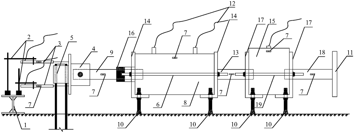
[0046] Embodiment 1 (application of single pile horizontal dead load test device), as figure 1 , 2 Shown:

[0047] 1) Select the reference point according to the test site conditions, set the reference beam 1, the length of the reference beam 1 is determined according to the position of the test pile, as long as possible, but its height-span ratio should not be less than 1 / 40, and the distance between the reference beam 1 and the test pile should not Less than 4 times the diameter of the test pile;

[0048] 2) Set the magnetic base 2 on the reference beam 1;

[0049] 3) Select the pile head fixing nut 5 according to the size of the test pile diameter, weld it with the π-shaped steel plate 4 and fix it on the pile head;

[0050] 4) Pass the steel bar through the reserved hole of the π-shaped steel plate 4 and the reserved hole at the left end of the first force transmission shaft 9, and fix it with nuts on the outside of the π-shaped steel plate 4;

[0051] 5) Pass the two ...

Embodiment 2

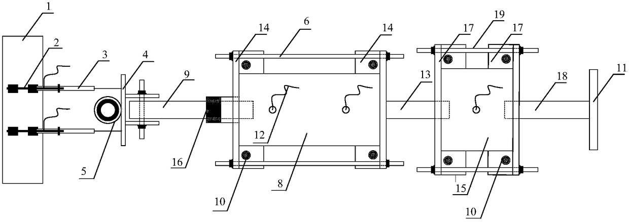
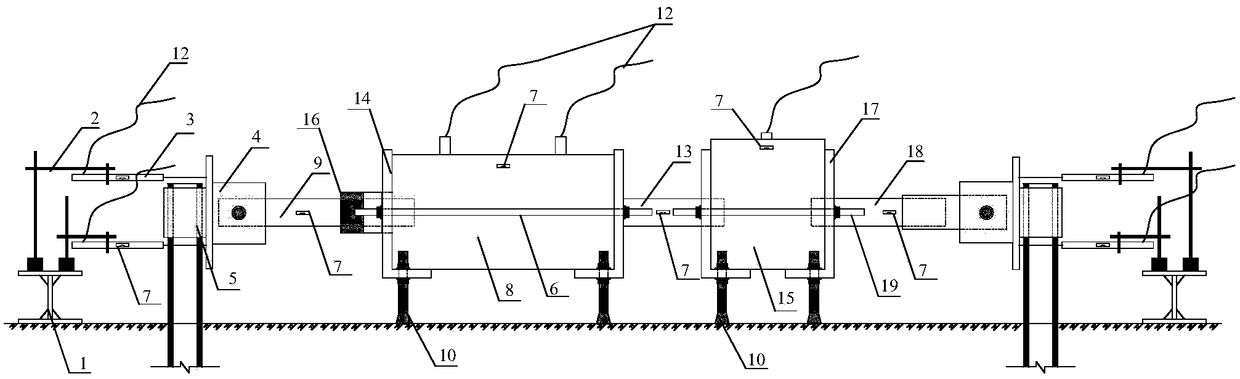
[0060] Embodiment 2 (the application of double pile horizontal dead load test device), as image 3 , 4 Shown:

[0061] 1) Select the reference point according to the test site conditions, set the reference beam 1, the length of the reference beam 1 is determined according to the position of the test pile, as long as possible, but its height-span ratio should not be less than 1 / 40, and the distance between the reference beam 1 and the test pile should be Not less than 4 times the diameter of the test pile;

[0062] 2) Set the magnetic base 2 on the reference beam 1;

[0063] 3) Select the pile head fixing nut 5 according to the diameter of the test pile on the left side, weld it with the π-shaped steel plate 4 and fix it on the pile head;

[0064] 4) Pass the steel bar through the reserved hole of the π-shaped steel plate 4 and the reserved hole at the left end of the first force transmission shaft 9, and fix it with nuts on the outside of the π-shaped steel plate 4;

[006...


PUM


Abstract

The invention relates to a mini pile horizontal static load test device and method. The device comprises a datum beam, magnetic gauge stands, displacement sensors, an n-shaped steel plate, a pile head fixing nut, a first fixing support, level pipes, a hydraulic jack, a first force transmission shaft, liftable supports, a counter-force device end plate, an oil inlet pipe, first L-shaped steel plates, a load sensor, second L-shaped steel plates, a third force transmission shaft and a second fixing support. The hydraulic jack is supported and fixed by means of cooperation of the first L-shaped steel plates arranged at the two ends of the hydraulic jack, the first fixing support and the corresponding liftable supports. The load sensor is supported and fixed by means of cooperation of the second L-shaped steel plates arranged at the two ends of the load sensor, the second fixing support and the corresponding liftable supports. The load sensor is connected with the counter-force device end plate through the third force transmission shaft. According to the mini pile horizontal static load test device and method, during the mini pile horizontal static load test, force transmission is completely horizontal, horizontal displacement of the pile end of a mini pile can be detected accurately, mounting and adjusting are convenient, the height of the supports can be adjusted, and the device and method are suitable for pile heads of any height and can carry out dual pile testing at the same time.

Description

technical field [0001] The invention relates to the field of foundation pile detection, in particular to a micro-pile horizontal static load test device and method. Background technique [0002] Micro-piles refer to piles with a diameter of less than 300mm. Under normal conditions, the diameter of the micro-piles is between 70 and 300mm, and the slenderness ratio is greater than 30. The reinforced concrete piled by auger drilling, strong reinforcement and pressure grouting technology is poured in situ. pile. Due to the simple technology and convenient construction of micropile, it has developed rapidly in recent years and is widely used in various civil engineering projects, such as underpinning of building foundations, deep excavation of foundation pit support, stability of underground continuous wall trenches and prevention of landslides Wait. In applications such as landslide control, micropiles are mainly subjected to horizontal loads, so the determination of horizonta...

Claims


Application Information

Patent Timeline
Patent Type & Authority Patents(China)
IPC IPC(8): E02D33/00
CPCE02D33/00
Inventor 吴文兵刘浩官文杰段亚茹李博张凯顺邢康宇
Owner CHINA UNIV OF GEOSCIENCES (WUHAN)
Why Eureka
Try Eureka