Gas-liquid damping cylinder

A gas-liquid damping cylinder and cylinder tube technology, which is applied in the direction of cylinder, piston rod, fluid pressure actuating device, etc., can solve the problems of complex external structure, centrifuge failure, difficult to clean, etc., and achieve simple external structure and stable expansion and contraction speed. , the effect of easy installation

Active Publication Date: 2017-03-08
苏州盛天力离心机制造有限公司
View PDF7 Cites 4 Cited by
  • Summary
  • Abstract
  • Description
  • Claims
  • Application Information

AI Technical Summary

Problems solved by technology

[0003] For the automatic scraper centrifuge, the scraper device driven by the built-in hydraulic cylinder is currently used, and there are many oil pipes connected to the outside. During the use and maintenance process, it is impossible to guarantee that the hydraulic oil will not leak, so it is difficult to meet this standard.
[0004] If a scraper device driven by a built-in cylinder is used, although it can meet the requirements of cleanliness and easy cleaning, the speed of expansion and contraction of the piston rod of the cylinder is not easy to control, which may easily cause centrifuge failure, and there are also uncertainties in safety
[0005] There is a gas-hydraulic damping cylinder on the market. The telescoping speed of the piston rod of this gas-hydraulic damping cylinder becomes stable under the action of hydraulic damping, making it easy to control. However, the gas-hydraulic damping cylinder currently on the market consists of two series It is composed of cylinders, and the air inlet and air outlet are respectively set at the two ends of the two cylinders that are far away from each other, and the two cylinders are fixed by adding a few tie rods outside. Such a complex external structure makes it difficult to clean , it is difficult to build it inside the scraper box

Method used


Image

  • Gas-liquid damping cylinder

Examples


Embodiment Construction

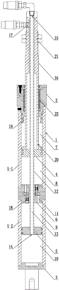
[0016] Specific embodiments of the present invention will be described in detail below in conjunction with the accompanying drawings.

[0017] like figure 1 The gas-liquid damping cylinder shown includes a tubular cylinder 1, which is composed of an upper cylinder 1-1 and a lower cylinder 1-2 arranged coaxially, and the upper cylinder 1-1 and the lower cylinder 1-2 A partition block 6 is sealingly connected between them, a cylinder plug 2 is arranged on the upper end of the upper cylinder body 1-1, a bottom cover 3 is sealingly connected to the lower end of the lower cylinder body 1-2, and an upper piston is slidingly arranged inside the upper cylinder body 1-1 4. A lower piston 5 is slidingly installed in the lower cylinder 1-2, a closed upper air cavity 7 is formed between the upper piston 4 and the cylinder plug 2, and a closed oil upper cavity is formed between the upper piston 4 and the partition block 6 8. A closed lower oil chamber 9 is formed between the partition blo...


PUM


Abstract

The invention discloses a gas-liquid damping cylinder. The gas-liquid damping cylinder comprises a cylinder barrel; an upper piston, a separation block and a lower piston are slidingly arranged in the cylinder barrel in sequence for dividing an inner cavity of the cylinder barrel to an upper gas cavity, an upper oil cavity, a lower oil cavity and a lower gas cavity; multiple channels for communicating the upper oil cavity with the lower oil cavity are formed in the separation block; a piston rod with the upper end extending out of the cylinder barrel is arranged in the cylinder barrel; the upper piston and the lower piston fixedly coat the piston rod; the piston rod is slidingly connected with the separation block; a lower gas port for communicating the lower gas cavity with the external is formed in the piston rod; and the external of the piston rod is coated with a gas pipe for communicating the upper gas cavity with the external. The cylinder barrel of the gas-liquid damping cylinder is an integral structure, or is connected only through the separation block, so that the external structure is simple, and the cleaning is easy; and the intake port communicated with the gas pipe of the upper gas cavity and the upper gas port communicated with the gas way of the lower gas cavity are both positioned at the same one end of the gas-liquid damping cylinder, so that the gas-liquid damping cylinder is more convenient to install.

Description

technical field [0001] The invention belongs to the fields of general hydraulic technology and pneumatic technology, and specifically relates to a gas-liquid damping cylinder. Background technique [0002] The GMP workshop of the pharmaceutical factory has high requirements on the cleanliness of the equipment, and the relevant parts of the equipment are required to be hygienic without dead ends and easy to clean. [0003] As for the automatic scraper centrifuge, the scraper device driven by a built-in hydraulic cylinder is currently used, and there are many oil pipes connected to it externally. During use and maintenance, it is impossible to guarantee that the hydraulic oil will not leak, so it is difficult to meet this standard. [0004] If a scraper device driven by a built-in cylinder is used, although it can meet the requirements of cleanliness and easy cleaning, the speed of expansion and contraction of the cylinder piston rod is not easy to control, which may easily ca...

Claims


Application Information

Patent Timeline
Patent Type & Authority Applications(China)
IPC IPC(8): F15B15/14F15B15/22F16J10/02F16J7/00
CPCF15B15/14F15B15/1428F15B15/1447F15B15/1457F15B15/149F15B15/22
Inventor 陈志才
Owner 苏州盛天力离心机制造有限公司
Why Eureka
Try Eureka