Supercharge Your Innovation With Domain-Expert AI Agents!

Touch panel

一种触摸面板、面侧的技术,应用在仪器、应用、其他家里用具等方向

Active Publication Date: 2017-03-08
MURATA MFG CO LTD
View PDF8 Cites 2 Cited by
  • Summary
  • Abstract
  • Description
  • Claims
  • Application Information

AI Technical Summary

Problems solved by technology

That is, when the pressing position is on the first straight line or the second straight line, the pressing cannot be detected properly.

Method used


Image

  • Touch panel
  • Touch panel
  • Touch panel

Examples


Embodiment Construction

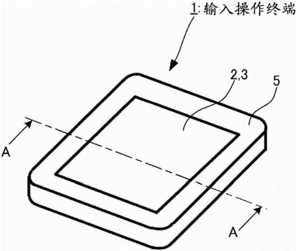
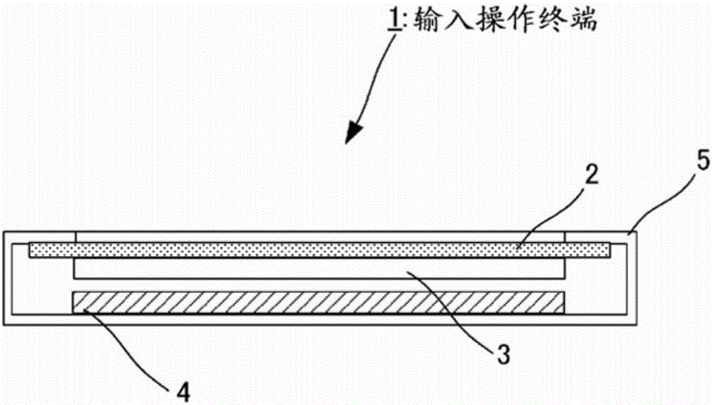
[0041] Hereinafter, a touch panel as an embodiment of the present invention will be described. figure 1 It is a schematic diagram showing the appearance of an input operation terminal including a touch panel according to this example. figure 2 Yes figure 1 A cross-sectional view along direction A-A is shown. The input operation terminal 1 according to this example has a configuration in which a touch panel 2 , a display 3 , and a control board 4 are mounted in a housing 5 . box 5 as figure 1 As shown, it has a substantially rectangular parallelepiped shape. Box 5 is in figure 1 The upper surface of the center has the shape of a rectangular opening. In this example, the open face is approximately square.

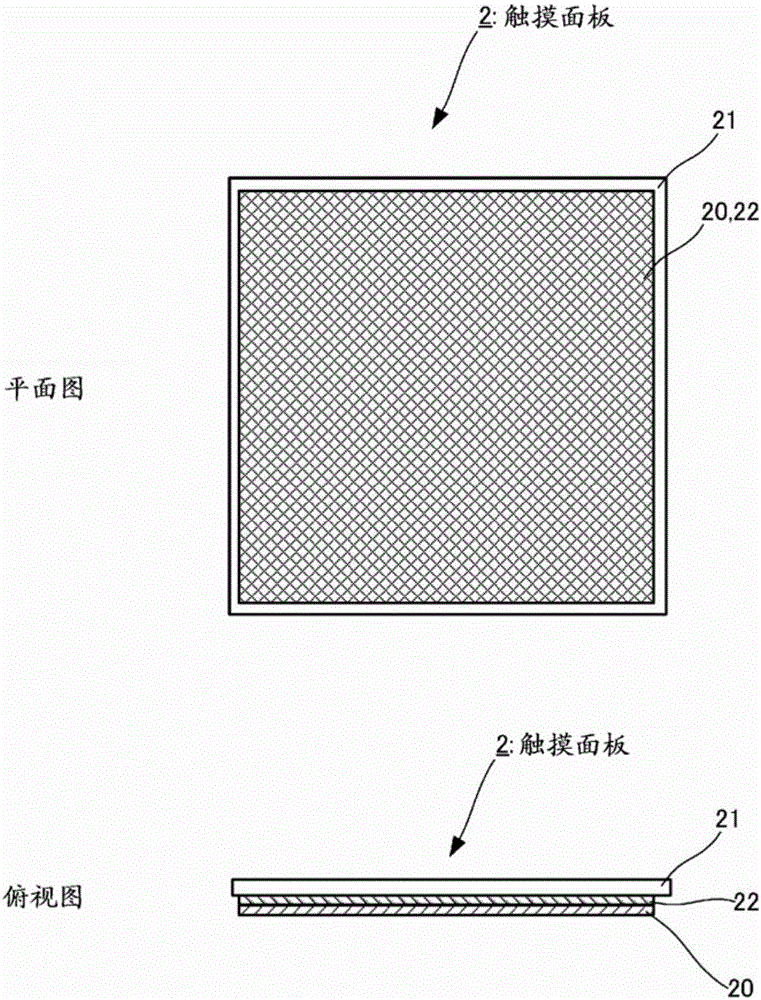
[0042] The touch panel 2 is mounted such that a first main surface described below closes a rectangular opening formed on the upper surface of the housing 5 . That is, the first main surface is exposed through the opening surface of the frame body 5 . In addition, a di...


PUM


Abstract

A touch panel provided with a first main surface and a second main surface that oppose each other. The first main surface is an operation surface. The touch panel is also provided with a panel member (21) where a deformation is caused by a pressing force on the operation surface; a main functional part (20) comprising a flat membrane type piezoelectric film (200), which is provided with a mutually opposed third main surface and fourth main surface, on both of which surfaces are arranged piezoelectric voltage-detecting electrodes that detect the piezoelectric voltage corresponding to the amount of deformation in the piezoelectric film (200); and an adhesive layer (22) that is formed between the second main surface of the panel member (21) and the third main surface of the piezoelectric film (200) and bonds together the panel member (21) and the main functional part (20), causing the second main surface of the panel member (21) to oppose the third main surface of the piezoelectric film (200). The surface of the adhesive layer (22) that faces the third main surface of the piezoelectric film (200) is divided into multiple regions and has at least 1 combination of 2 regions in which the elastic moduli differ.

Description

technical field [0001] The present invention relates to a touch panel that detects a pressing operation on an operation surface by an operator. Background technique [0002] Conventionally, a touch panel has been proposed in which an operator touches a flat operation surface with a finger or the like, and simultaneously detects the touched position and the pushing amount (pressing force) at the time of touching. [0003] For example, Patent Document 1 describes that a capacitance detection electrode is disposed on at least either one of the first main surface side or the second main surface side of a piezoelectric thin film, and A thin touch panel in which piezoelectric voltage detection electrodes are arranged on the first main surface side and the second main surface side to simultaneously detect a touch position and a pushing amount. The operation surface is the first main surface side. [0004] In addition, in Patent Document 2, it is described that by arranging capaci...

Claims


Application Information

Patent Timeline
Patent Type & Authority Applications(China)
IPC IPC(8): G06F3/041G06F3/044
CPCB32B7/12B32B25/08B32B25/12B32B25/20B32B27/08B32B27/18B32B27/283B32B27/308B32B27/32B32B27/36B32B27/365B32B2250/44B32B2307/20B32B2307/412B32B2307/516B32B2307/704B32B2307/732B32B2457/208G06F3/0445G06F3/0446G06F2203/04105G06F2203/04106G06F2203/04103
Inventor 安藤正道森健一
Owner MURATA MFG CO LTD
Features
  • R&D
  • Intellectual Property
  • Life Sciences
  • Materials
  • Tech Scout
  • Unparalleled Data Quality
  • Higher Quality Content
  • 60% Fewer Hallucinations
Learn More