

Piezoelectric actuator driving device and method
a piezoelectric actuator and driving device technology, applied in the direction of electric control, machines/engines, generators/motors, etc., can solve the problems of degrading driving accuracy and crs cannot achieve expected performance, and achieve the effect of improving the driving accuracy of piezoelectric actuators
- Summary
- Abstract
- Description
- Claims
- Application Information
AI Technical Summary
Benefits of technology
Problems solved by technology
Method used
Image

Examples
first embodiment
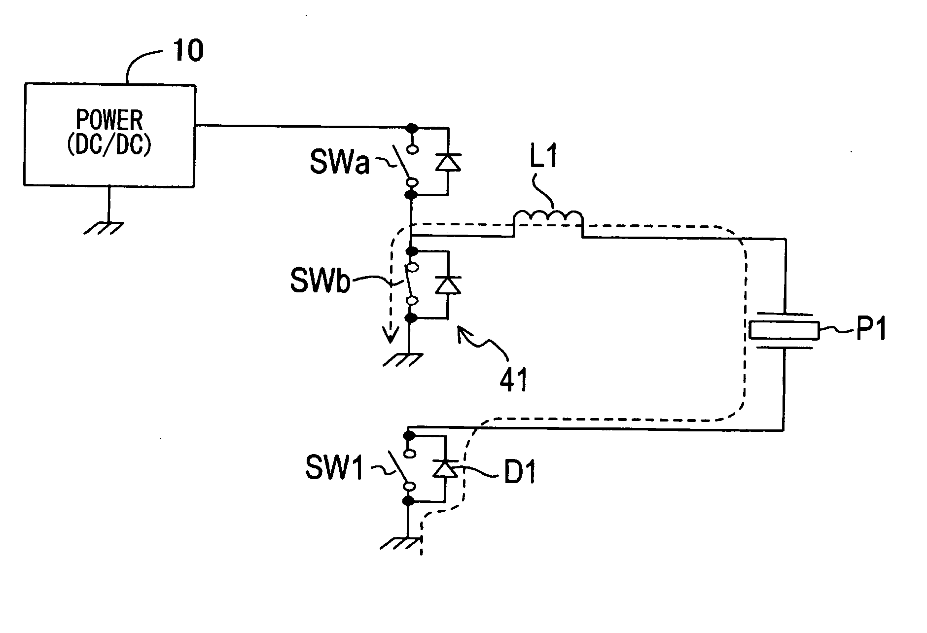
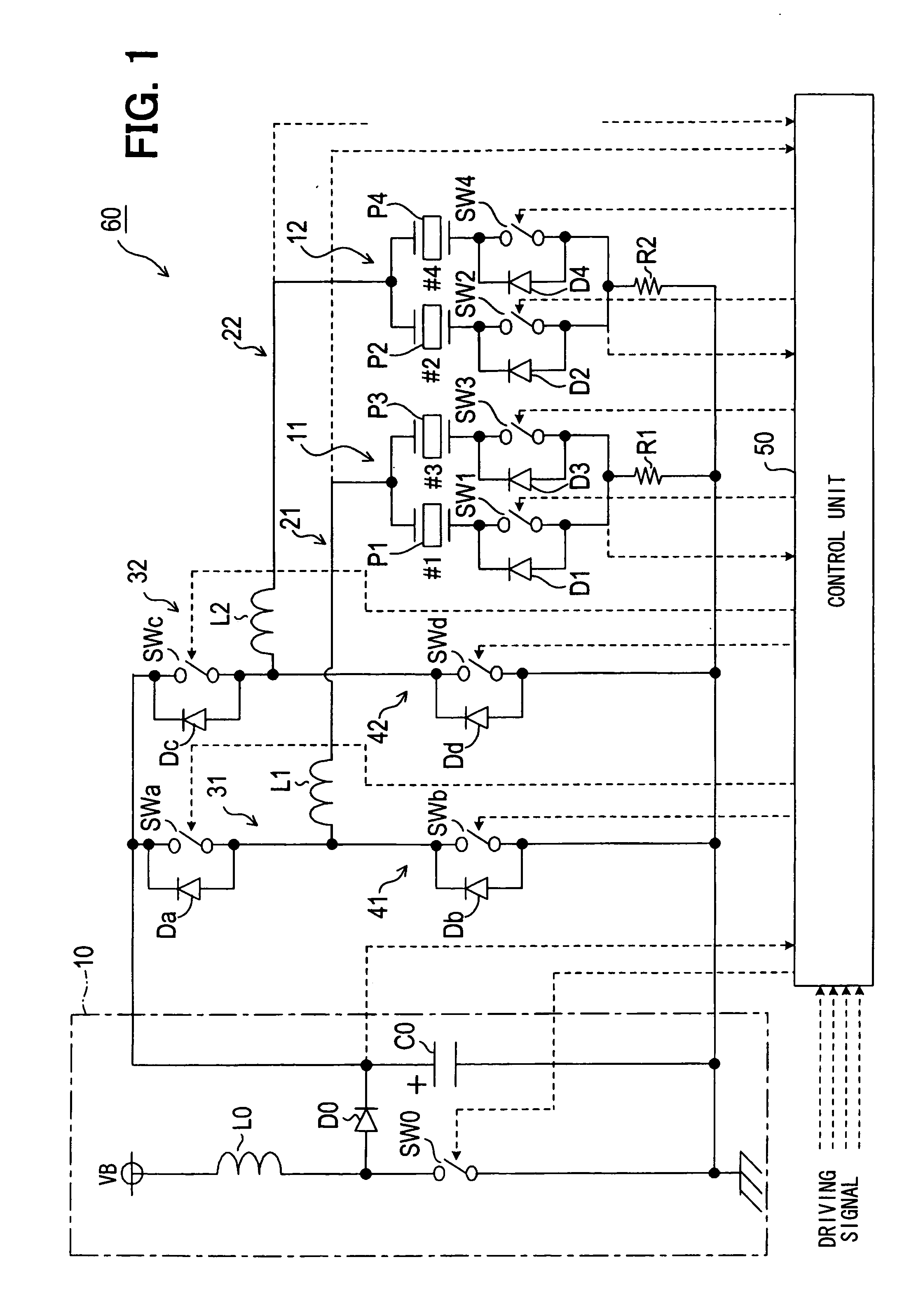
[0038]Referring first to FIG. 1, a piezoelectric actuator driving device 60 is used in a fuel injection system for a diesel engine mounted in a vehicle. It is so constructed that the following is implemented: piezoelectric actuators P1 to P4 provided in respective injectors for injecting high-pressure fuel from a common rail into the respective cylinders of the diesel engine are charged and discharged and thereby expanded or contracted; and the injector of each cylinder is thereby caused to start and stop fuel injection. The number of cylinders of the engine is assumed to be four, and piezoelectric actuator Pn (n is any of 1 to 4) corresponds to the n-th cylinder (hereafter, also specified as #n). Further, in the driving device 60, the cylinders of the engine are grouped by two. The first cylinder #1 and the third cylinder #3 are grouped into a first group, and the second cylinder #2 and the fourth cylinder #4 are grouped into a second group.
[0039]The driving device 60 includes the ...
second embodiment
[0089]In a second embodiment illustrated in FIG. 7, the driving device 60 is differentiated from the first embodiment in the following points.
[0090](1) The inductor L2, charging switch SWc, and the discharging switch SWd are not provided. The inductor L1 and the parallel circuit 11 (piezoelectric actuators P1, P3) of the first group are connected with each other through a switch SW5. The inductor L1 and the parallel circuit 12 (piezoelectric actuators P2, P4) of the second group are connected with each other through a switch SW6. That is, the driving device 60 is provided with only a set of the inductor L1, the charging switch SWa, and the discharging switch SWb. The inductor L1 is connected switchably to either of the parallel circuits 11, 12 of the two groups by the switches SW5, SW6. The group of piezoelectric actuators connected in series with the inductor L1 is switched between the first group and the second group. For this reason, hereafter, the switches SW5, SW6 will be desig...
third embodiment
[0102]In a third embodiment, the driving device 60 is constructed in the same circuit configuration as the second embodiment illustrated in FIG. 7. However, the driving device 60 in the third embodiment is differentiated only in the point of controlling the group selector switches SW5 and SW6 as illustrated in FIG. 9.
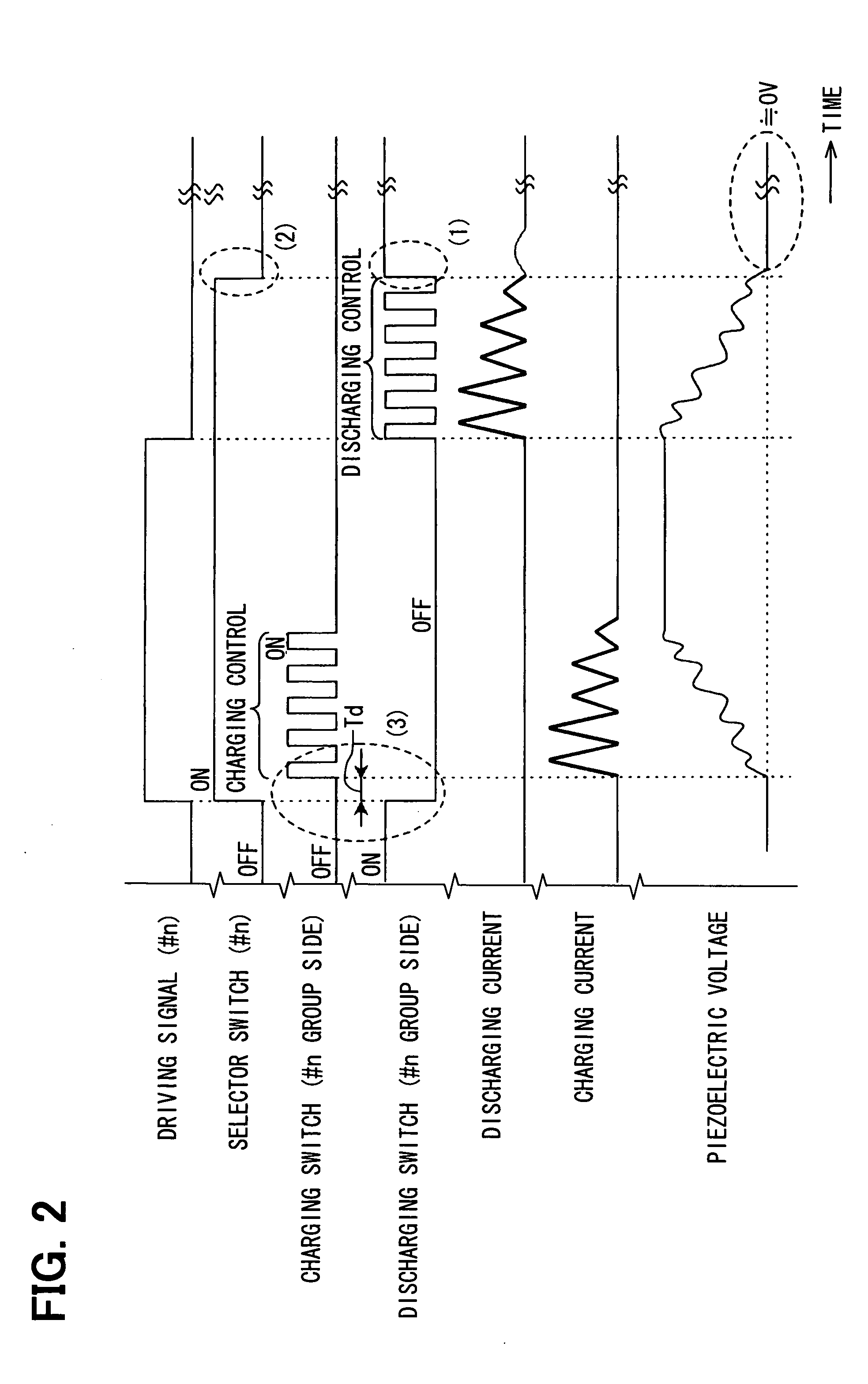
[0103]That is, during the period for which multistage injection into #n should be carried out, the control unit 50 does not turn on both the charge enabling switch and the discharge enabling switch forming the group selector switch for the group of #n. Instead, it turns on the charge enabling switch and the discharge enabling switch as follows: when the driving signal for #n is high, the control unit 50 turns on only the charge enabling switch; and when the driving signal for #n is low, it turns on only the discharge enabling switch.
[0104]Similarly with FIG. 8, FIG. 9 also illustrates the situation that occurs when the driving signal for #n is changed high for the first...
PUM
 Abstract
Description
Claims
Application Information