
A high-low speed pulley switching device

A switching device, high and low speed technology, applied in the direction of transmission, belt/chain/gear, metal processing, etc., can solve the problems of troublesome installation and disassembly, complex transmission ratio structure, poor operation stability, etc., to achieve convenient installation and disassembly, convenient high-speed The effect of large transmission and transmission load

Active Publication Date: 2018-11-02
ANHUI CHIZHOU HOUSEHOLD MACHINE TOOL
View PDF6 Cites 0 Cited by
  • Summary
  • Abstract
  • Description
  • Claims
  • Application Information

AI Technical Summary

Problems solved by technology

[0002] With the rapid development of industry, the shape requirements of mechanical parts are ever-changing, and the practical requirements of machine tools are also getting higher and higher. Almost any machine tool needs to realize various speed requirements, and the speed change method of machine tools mostly adopts slip Gears and other methods are more common, and some machine tools can also use pulleys of different sizes to realize the change of the transmission ratio. The traditional belt transmission method to change the transmission ratio has a complicated structure, troublesome production, troublesome installation and disassembly, and inconvenient operation. It is inconvenient to fix, the resistance is large when the parts are transmitted, the installation and disassembly of the traditional tie rods are very troublesome, and the operation stability is poor

Method used


Image

  • A high-low speed pulley switching device

Examples


Embodiment Construction

[0013] In order to make it easy to understand the technical means, creative features, objectives and effects achieved by the present invention, the present invention will be further explained below in conjunction with specific drawings.

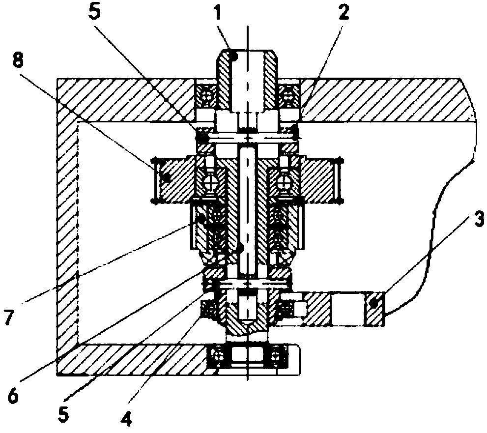
[0014] A high-low-speed pulley switching device, which includes an input shaft 1, an upper coupling tooth 2, a shift fork 3, a lower coupling tooth 4, a cylindrical pin 5, a pull rod 6, a small pulley 7, a large pulley 8, and two of the input shaft 1. The end is installed in the box hole, the tie rod 6 is installed in the input shaft 1, the upper coupling tooth 2 is installed on the upper part of the input shaft 1, the tie rod 6 and the upper coupling tooth 2 are fixedly connected by a cylindrical pin 5, and the large pulley 8 passes through the bearing Installed on the hollow sleeve on the input shaft 1, under the upper coupling tooth 2, a small pulley 7 is installed under the large pulley 8, and a lower coupling tooth 4 is installed under the s...


PUM


Abstract

The invention discloses a high-low speed switching device with belt wheels and belongs to the technical field of design of mechanical devices. The high-low speed switching device comprises an input shaft, an upper conjunction gear, a shifting fork, a lower conjunction gear, cylindrical pins, a pull rod, the small belt wheel and the large belt wheel, wherein two ends of the input shaft are arranged in box body holes; the pull rod is arranged in the input shaft; the upper conjunction gear is arranged at the upper part of the input shaft; the pull rod is fixedly connected with the upper conjunction gear by adopting one cylindrical pin; the large belt wheel is arranged on a shaft sleeve arranged on the input shaft in a clearance sleeving mode by a bearing and is positioned below the upper conjunction gear; the small belt wheel is arranged below the large belt wheel; the lower conjunction gear is arranged below the small belt wheel; the lower conjunction gear is fixedly connected with the pull rod by adopting the other cylindrical pin; the pull rod is connected together with the shifting fork; and high-low speed driving switching is realized by vertical movement of the shifting fork. The high-low speed switching device disclosed by the invention has the advantages of simplicity in manufacturing, convenience and quickness in use, convenience in mounting and dismounting, flexible movement, convenience in high-low speed switching and great driving load.

Description

Technical field [0001] The invention relates to the technical field of mechanical device design, in particular to a high-low-speed pulley switching device. Background technique [0002] With the rapid development of industry, the requirements for the shape of mechanical parts are ever-changing, and the practical requirements of machine tools are getting higher and higher. Almost any machine tool needs to achieve a variety of speed requirements, and the speed change method of the machine tool is mostly slip. Gears and other methods are more common. Some machine tools can also use different sizes of pulleys to change the transmission ratio. The traditional belt transmission method changes the transmission ratio. The structure is complicated, the production is troublesome, the installation and disassembly are troublesome, the operation is inconvenient, and the transmission parts are inconvenient. It is inconvenient to fix, the resistance is large when the transmission parts are tran...

Claims


Application Information

Patent Timeline
Patent Type & Authority Patents(China)
IPC IPC(8): B23Q5/00F16H37/12
CPCB23Q5/00F16H37/12
Inventor 陶帅陈关元
Owner ANHUI CHIZHOU HOUSEHOLD MACHINE TOOL
Learn More