Traction wheel of elevator
A technology of elevator traction and traction wheels, which is applied to elevators, hoisting devices, transportation and packaging in buildings, etc. It can solve the problems of brake device wear, potential safety hazards, and inability to use high loads, etc. Effects of pressure, safety assurance, and service life extension
- Summary
- Abstract
- Description
- Claims
- Application Information
AI Technical Summary
Problems solved by technology
Method used
Image
Examples
Embodiment 1
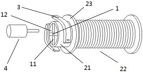
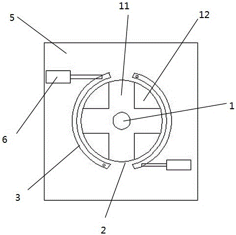
[0015] Embodiment 1: An elevator traction wheel, the traction wheel includes a cylindrical wheel body 2 and a hollow bushing 1 coaxially arranged with the wheel body 2; Connected by several spokes 11 distributed perpendicular to the circumferential direction of the wheel body 2; the wheel body 2 is provided with two protective plates 23; the protective plates 23 divide the wheel body 2 into a brake segment 21 and a sheave segment 22; the braking section 21 is set with a braking device; the braking device includes a fixed plate 5, a brake pad 3 and a hydraulic rod 6; the brake pad 3 is an arc-shaped structure, and the brake pad 3 One end of one end is movably connected with the fixed plate 5; the other end of the brake pad 3 is movably connected with the extension rod of the hydraulic rod 6; the hydraulic rod 6 is fixedly arranged on the fixed plate 5; 6 can be pressed to the brake segment 21 or leave the brake segment 21.
Embodiment 2
[0016] Embodiment 2: An elevator traction wheel, the traction wheel includes a cylindrical wheel body 2 and a hollow bushing 1 coaxially arranged with the wheel body 2; Connected by several spokes 11 distributed perpendicular to the circumferential direction of the wheel body 2; the wheel body 2 is provided with two protective plates 23; the protective plates 23 divide the wheel body 2 into a brake segment 21 and a sheave segment 22; the braking section 21 is set with a braking device; the braking device includes a fixed plate 5, a brake pad 3 and a hydraulic rod 6; the brake pad 3 is an arc-shaped structure, and the brake pad 3 One end of one end is movably connected with the fixed plate 5; the other end of the brake pad 3 is movably connected with the extension rod of the hydraulic rod 6; the hydraulic rod 6 is fixedly arranged on the fixed plate 5; 6 can be pressed to the braking segment 21 or away from the braking segment 21, and the sheave segment 22 is provided with annu...
Embodiment 3
[0017] Embodiment 3: An elevator traction wheel, the traction wheel includes a cylindrical wheel body 2 and a hollow bushing 1 coaxially arranged with the wheel body 2; Connected by several spokes 11 distributed perpendicular to the circumferential direction of the wheel body 2; the wheel body 2 is provided with two protective plates 23; the protective plates 23 divide the wheel body 2 into a brake segment 21 and a sheave segment 22; the braking section 21 is set with a braking device; the braking device includes a fixed plate 5, a brake pad 3 and a hydraulic rod 6; the brake pad 3 is an arc-shaped structure, and the brake pad 3 One end of one end is movably connected with the fixed plate 5; the other end of the brake pad 3 is movably connected with the extension rod of the hydraulic rod 6; the hydraulic rod 6 is fixedly arranged on the fixed plate 5; 6 can be pressed to the brake segment 21 or leave the brake segment 21, the sheave segment 22 is provided with an annular ridge...
PUM
 Abstract
Description
Claims
Application Information
 - R&D Engineer
- R&D Manager
- IP Professional
- Industry Leading Data Capabilities
- Powerful AI technology
- Patent DNA Extraction
Browse by: Latest US Patents, China's latest patents, Technical Efficacy Thesaurus, Application Domain, Technology Topic, Popular Technical Reports.
© 2024 PatSnap. All rights reserved.Legal|Privacy policy|Modern Slavery Act Transparency Statement|Sitemap|About US| Contact US: help@patsnap.com


