Rolling mill roller moving support structure

A technology for moving a support and a calender, which is used in glass calendering, glass manufacturing equipment, glass forming, etc., can solve the problems of difficult to guarantee the forming quality, uneven glass liquid, etc., to save adjustment time, reduce production costs, The effect of reducing the difficulty of processing

Active Publication Date: 2017-03-15
BENGBU TRIUMPH ENG TECH CO LTD
View PDF5 Cites 0 Cited by
  • Summary
  • Abstract
  • Description
  • Claims
  • Application Information

AI Technical Summary

Problems solved by technology

In this way, when the lip brick is replaced on the production line, if the installation of the new lip brick cannot be guaranteed to be parallel to the edge of the furnace or the guide rail of the calender, the molten glass will be uneven when entering the calender roller, and the forming quality will be difficult to guarantee.

Method used


Image

  • Rolling mill roller moving support structure
  • Rolling mill roller moving support structure

Examples


Embodiment Construction

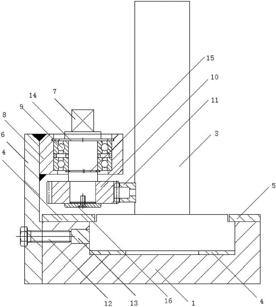
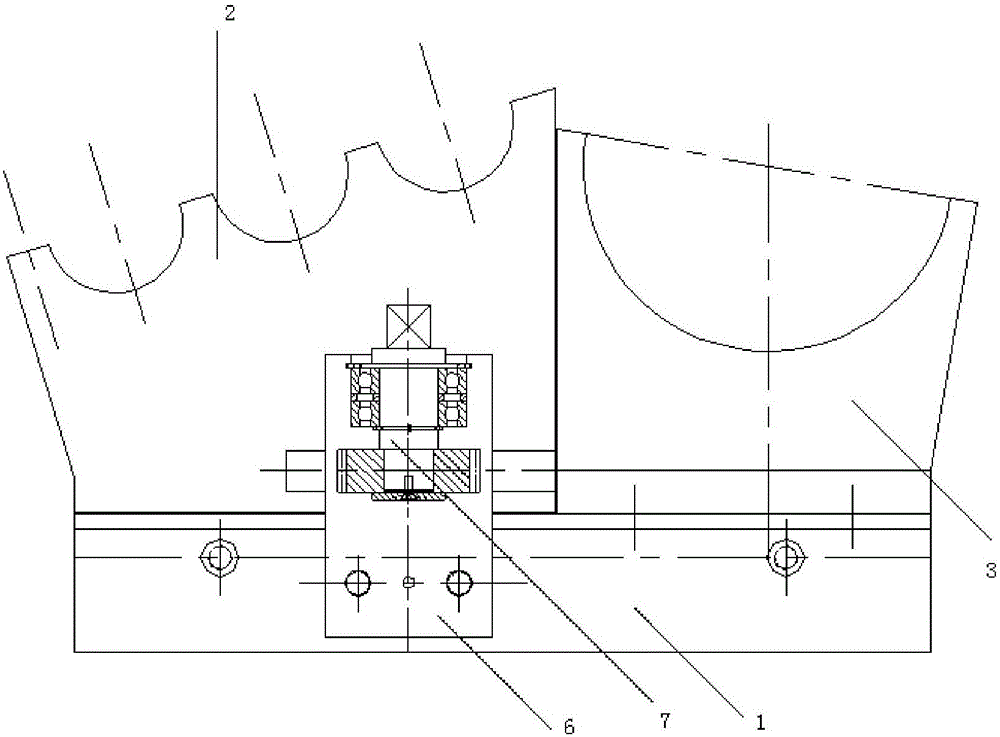
[0015] As shown in the figure, a calender and roller moving support structure includes a support body, a moving adjustment device, and a locking device. The support body includes a base 1, a lower roll support 2, and an auxiliary roll support 3. The roll support 2 is used to support the lower calender roll of the calender, the auxiliary roll support 3 is used to support the auxiliary roll of the calender, the lower roll support 2 is fixed on the auxiliary roll support 3, and the bottom end of the auxiliary roll support 3 is fixedly installed with Slide rail 4, slide rail 4 is slidingly fitted in the chute installed on the upper end of base 1, pressing plate 1 4 and pressing plate 2 5 are respectively pressed on both sides of auxiliary roller support 3, and fixed on the upper end surface of base 1;

[0016] The mobile adjustment device includes a fixed seat 6 and a rotating shaft 7, the fixed seat 6 is fixed on the side of the base 1, the inner surface of the upper end of the fi...


PUM


Abstract

The invention discloses a rolling mill roller moving support structure. The structure comprises a support body, a moving adjusting device and a locking device, wherein the support body comprises a base, a lower roller support and an auxiliary roller support; the lower roller support is used for supporting a rolling mill lower rolling roller; the auxiliary roller support is used for supporting a rolling mill auxiliary roller; the lower roller support is fixed on the auxiliary roller support; a sliding rail is fixedly mounted at the bottom end of the auxiliary roller support; the sliding rail is glidingly matched with the interior of a sliding chute in the upper end of the base; a pressing plate I and a pressing plate II are respectively pressed on the two sides of the auxiliary roller support and are fixed on the upper end surface of the base; a rotating shaft is rotated through a spanner or a special tool, so that a gear rotates; as the gear is fixed on the base through the rotating shaft and a fixed seat, a roller support is driven to move with a rack. Moving adjustment of the roller support is realized, and the adjustment time is greatly shortened.

Description

technical field [0001] The invention relates to the field of glass machinery, in particular to a calender roller moving support structure of a calender glass production line. Background technique [0002] The roller support of the calender used in the usual rolled glass production line is fixed, and only the upper roller support can be moved. The installation of the lip brick is required to be parallel to the edge of the melting furnace and the wheel guide rail of the calender. In this way, when the lip brick is replaced in the production line, if the installation of the new lip brick cannot be guaranteed to be parallel to the edge of the furnace or the guide rail of the calender, the molten glass will be uneven when entering the calender roll, and the forming quality will be difficult to guarantee. At present, the wheels of some calenders on the market can move left and right. When the lip brick and the guide rail of the calender deviate, the position of the wheels can be a...

Claims


Application Information

Patent Timeline
IPC IPC(8): C03B13/18
CPCC03B13/18
Inventor 梁超帝程海波夏鹏华张德三刘雨虹纪圣杰何思源耿职唐中朝王松
Owner BENGBU TRIUMPH ENG TECH CO LTD
Why Eureka
Try Eureka