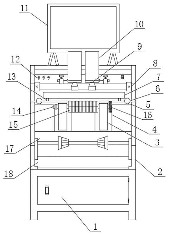
Mold switching device of printing equipment

A technology for switching devices and printing equipment, applied in printing, printing presses, general parts of printing machinery, etc., can solve the problems of inconvenient disassembly and assembly, difficult adjustment of mold roll size, inaccurate glue plate attachment, etc., to improve accuracy speed, improve efficiency and safety, and the effect of fast mold placement

Pending Publication Date: 2022-07-05
广东潮华龙印刷有限公司
View PDF0 Cites 0 Cited by
  • Summary
  • Abstract
  • Description
  • Claims
  • Application Information

AI Technical Summary

Problems solved by technology

[0004] The purpose of the present invention is to provide a mold switching device for printing equipment, which aims to improve the existing molds used on printing equipment. Before the molds are put on the machine, the gears of the molds need to be disassembled, and then installed after the plate is attached, resulting in its disassembly operation. It is inconvenient, and during the printing process, the size of the mold roller is not easy to adjust, and the rubber plate is not attached accurately, so the amount of it entering the printing machine will also change accordingly, which may have an adverse effect on the printing effect

Method used


Image

  • Mold switching device of printing equipment

Examples


Embodiment Construction

[0017] Embodiments of the present invention are described in detail below, examples of which are illustrated in the accompanying drawings, wherein the same or similar reference numerals refer to the same or similar elements or elements having the same or similar functions throughout. The embodiments described below with reference to the accompanying drawings are exemplary, only used to explain the present invention, and should not be construed as a limitation of the present invention.

[0018] In the description of the present invention, it should be understood that the azimuth description, such as the azimuth or position relationship indicated by up, down, front, rear, left, right, etc., is based on the azimuth or position relationship shown in the drawings, only In order to facilitate the description of the present invention and simplify the description, it is not indicated or implied that the indicated device or element must have a particular orientation, be constructed and ...


PUM


Abstract

The invention discloses a printing equipment mold switching device which comprises a machine box, a machine frame is arranged at the top end of the machine box, longitudinal fixing blocks are symmetrically arranged in the machine frame, transverse fixing blocks are arranged on the longitudinal fixing blocks, a cover mold device assembly is arranged on the inner sides of the transverse fixing blocks, and a pressing plate platform is arranged on the machine frame. According to the mold switching device, mold switching equipment is improved, a plate mold roller can be directly placed in the mold switching platform conveniently, movement adjustment of a mold is achieved under driving of the air cylinder, rapid mold attaching is achieved, and therefore the operation efficiency and safety of the plate mold roller are improved; printed products with different thicknesses can be conveniently fixed through the mold switching platform, data can be conveniently transmitted to a data center, automatic amplification registration is realized, and the printing template registration accuracy of the products is improved; and positioning can be conveniently carried out according to the heights of the plate mold rollers of the printed products with different thicknesses through the limiting device, and therefore the lifting height of the air cylinder can be conveniently adjusted.

Description

technical field [0001] The invention relates to the technical field of printing equipment, in particular to a mold switching device for printing equipment. Background technique [0002] Printing is a process of transferring texts, drawings, photos and anti-counterfeiting manuscripts to plate making, inking and pressure, so that the ink is transferred to the surface of materials such as paper, fabric, plastic and leather, and the content of the manuscript is copied in batches. The approved printing plate is transferred to the substrate through printing machinery and special ink. [0003] However, the mold used in the existing printing equipment needs to disassemble the gear of the mold before it is put on the machine, and then install it after the plate is attached, which makes the disassembly and assembly operation relatively inconvenient, and during the printing process, the size of the mold roller is also It is not easy to adjust, and the glue plate is not attached accura...

Claims


Application Information

Patent Timeline
Patent Type & Authority Applications(China)
IPC IPC(8): B41F27/12
CPCB41F27/12
Inventor 廖绪佳连植锋廖伟龙
Owner 广东潮华龙印刷有限公司
Why Eureka
Try Eureka