Air deflector positioning structure and cooling fan with same

A technology of positioning structure and air deflector, which is applied in the positioning structure of air deflector and the field of cooling fans, and can solve the problems that the air deflector cannot be effectively positioned and the direction of the air outlet cannot be adjusted according to needs, etc.

Active Publication Date: 2017-03-15
GREE ELECTRIC APPLIANCES INC
View PDF23 Cites 2 Cited by
  • Summary
  • Abstract
  • Description
  • Claims
  • Application Information

AI Technical Summary

Problems solved by technology

[0003] Based on this, it is necessary to provide a positioning structure of the wind deflector that can be effectively positioned so that the wind outlet d

Method used


Image

  • Air deflector positioning structure and cooling fan with same
  • Air deflector positioning structure and cooling fan with same
  • Air deflector positioning structure and cooling fan with same

Examples


Embodiment Construction

[0038] In order to make the purpose, technical solution and advantages of the present invention clearer, the positioning structure of the air deflector and the cooling fan with it of the present invention will be further described in detail through the embodiments and with reference to the accompanying drawings. It should be understood that the specific embodiments described here are only used to explain the present invention, not to limit the present invention.

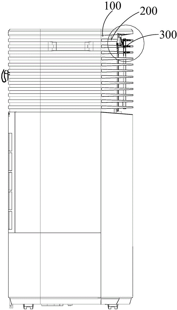
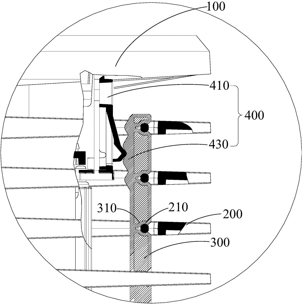
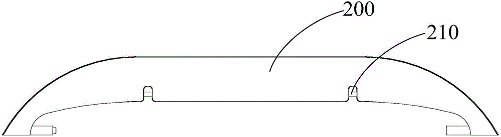
[0039] see figure 1 and figure 2 , The positioning structure of the air deflector in this embodiment can be applied to air-conditioning appliances such as cooling fans and air conditioners. The positioning structure of the air deflector comprises: an air outlet frame 100 and a group of mutually parallel air deflectors 200 arranged in the air outlet frame 100, and a positioning mechanism 400; Pivot connection, and all the air deflectors 200 are connected by connecting rods 300; the positioning mechanism 400 positio...


PUM


Abstract

The invention relates to the technical field of air adjustment, in particular to an air deflector positioning structure. The air deflector positioning structure comprises an air outlet frame, a set of parallel air deflectors arranged in the air outlet frame and a positioning mechanism; each air deflector is pivoted to the air outlet frame, and all the air deflectors are connected through a connecting rod; and the positioning mechanism limits movement of the connecting rod relative to the air outlet frame, and therefore the rotating angle of the air deflectors relative to the air outlet frame is further located. According to the air deflector positioning structure, when a user needs to change the air direction, one of the air deflector is pulled with the hand, and all the air deflectors synchronously rotate under driving of the connecting rod; in the rotating process, when the air deflectors rotate to a certain angle, due to the fact that movement of the connecting rod relative to the air outlet frame is limited by the positioning mechanism, rotation of the air deflectors relative to the air outlet frame is limited, and the different-angle air guide function of the air deflectors is achieved. The invention further provides a cooling fan.

Description

technical field [0001] The invention relates to the technical field of air conditioning, in particular to a positioning structure of an air deflector and a cooling fan having the same. Background technique [0002] In order to adjust the flow direction of the air, the air outlets of air-conditioning appliances such as cooling fans and air conditioners are equipped with wind deflectors to adjust the wind direction, so that cold air (or hot air) can be blown out in a set direction. The traditional horizontal wind deflector relies on manual control, and the positioning effect is achieved through the friction force between the rotating shaft of the wind deflector and the hole of the air outlet frame, so that the air outlet direction is maintained in one direction. After the electrical appliance is used for a long time, the rotating shaft and the hole become smooth due to long-term wear, and the friction between the two becomes smaller, making it difficult for the wind deflector ...

Claims


Application Information

Patent Timeline
IPC IPC(8): F24F13/15F24F5/00
CPCF24F5/0035F24F13/15Y02E60/14
Inventor 孙土春陈宇强李曙光侯剑飞黄波曾琦
Owner GREE ELECTRIC APPLIANCES INC
Why Eureka
Try Eureka