Ceiling fan

A ceiling fan and wind wheel technology, applied in the field of ceiling fans, can solve problems such as accidents, achieve the effects of improving energy efficiency, realizing the function of guiding air, and reducing the loss of air volume

Active Publication Date: 2021-01-12
GD MIDEA ENVIRONMENT APPLIANCES MFG +1
View PDF10 Cites 0 Cited by
  • Summary
  • Abstract
  • Description
  • Claims
  • Application Information

AI Technical Summary

Problems solved by technology

[0002] In the related art, the fan blades of the ceiling fan are exposed, and the user may come into contact with the high-speed rotating fan blades during the use of the ceiling fan, which may cause accidents.

Method used


Image

  • Ceiling fan
  • Ceiling fan
  • Ceiling fan

Examples


Embodiment 1

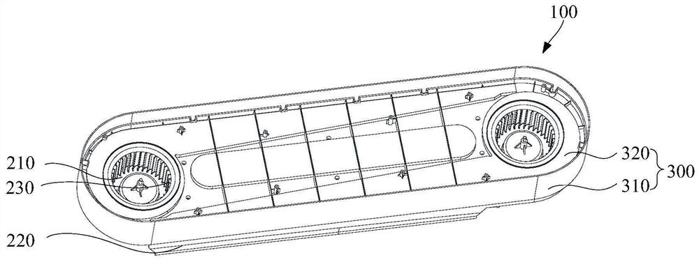
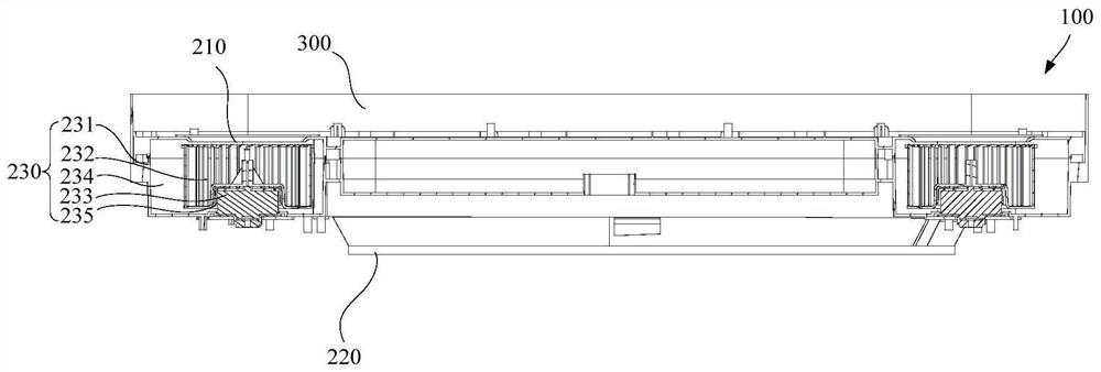
[0058] Such as Figure 1 to Figure 4 As shown, the first embodiment of the present invention provides a ceiling fan 100 , including: a casing 300 , a fan wheel assembly 230 and an air outlet duct 240 .

[0059] Wherein, the casing 300 is provided with an air outlet 220 , the fan wheel assembly 230 is arranged in the casing 300 , and the air outlet duct 240 is arranged in the casing 300 and connects the fan wheel assembly 230 and the air outlet 220 . During the operation of the ceiling fan 100 , the wind wheel assembly 230 runs in the casing 300 , and the casing 300 can prevent the user from directly contacting the running wind wheel assembly 230 . When the wind wheel assembly 230 is in operation, a certain wind pressure is generated, and the air flow is sent into the air outlet duct 240, and the air outlet duct 240 communicates with the air outlet 220 on the casing 300; when the air outlet duct 240 is full of air flow, the outlet The air pressure inside the air duct 240 rises...

Embodiment 2

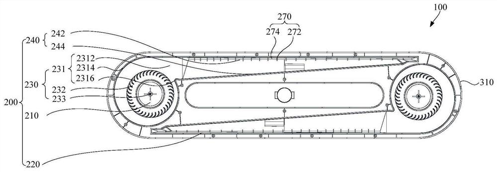
[0062] Such as Figure 1 to Figure 4 As shown, the second embodiment of the present invention provides a ceiling fan 100 , including: a casing 300 , a wind wheel assembly 230 and an air outlet duct 240 . Wherein, the casing 300 is provided with an air outlet 220 , the fan wheel assembly 230 is arranged in the casing 300 , and the air outlet duct 240 is arranged in the casing 300 and connects the fan wheel assembly 230 and the air outlet 220 .

[0063] Further, as figure 1 , figure 2 and Figure 4 As shown, in the height direction of the ceiling fan 100 , the air outlet 220 is located below the air outlet duct 240 , and the wind wheel assembly 230 is located on the side of the air outlet duct 240 .

[0064] In this embodiment, in the height direction of the ceiling fan 100, the air outlet 220 is located below the air outlet duct 240, so that the airflow in the air outlet duct 240 is discharged from the air outlet 220 located below the air outlet duct 240 to the The user su...

Embodiment 3

[0075] Such as Figure 4 As shown, in any of the above embodiments, further, the ceiling fan 100 further includes a flow guiding structure 250 .

[0076] In this embodiment, the air guiding structure 250 is connected to the air outlet duct 240 and extends toward the air outlet 220, so as to quickly guide the wind in the air outlet duct 240 to the air outlet 220 to deliver air to the user. It can further reduce the stagnation of the airflow in the air outlet duct 240, thereby reducing the loss of air volume and improving the air outlet effect. Specifically, the flow guide structure 250 is connected to the second air outlet wall surface 244 of the air outlet air channel 240 and is inclined toward the first air outlet wall surface 242 side.

[0077] Further, the air guiding structure 250 includes an air guiding surface 252 , and the air guiding surface 252 is inclined relative to the inner wall of the air outlet channel 240 .

[0078] On the one hand, the air guide surface 252 ...


PUM


Abstract

The invention provides a ceiling fan. The ceiling fan comprises a machine shell, a wind wheel assembly and an air outlet duct. An air outlet is arranged on the machine shell. The wind wheel assembly is arranged in the machine shell. The air outlet duct is arranged in the machine shell and communicates with the wind wheel assembly and the air outlet. The wind wheel assembly is arranged in the machine shell, so that the potential safety hazard that a user makes contact with the wind wheel assembly is eliminated. The air outlet duct is arranged in the machine shell and communicates with the windwheel assembly and the air outlet, the air guide function can be achieved, no matter what direction of air flow generated by the wind wheel assembly is, the air flow can be guided to the air outlet through the air outlet duct, the air volume loss is reduced, and the energy efficiency of the ceiling fan is improved.

Description

technical field [0001] The invention relates to the technical field of household appliances, in particular to a ceiling fan. Background technique [0002] In the related art, the fan blades of the ceiling fan are exposed, and the user may come into contact with the high-speed rotating fan blades during the use of the ceiling fan, which may cause accidents. Contents of the invention [0003] The present invention aims to solve at least one of the technical problems existing in the prior art. [0004] Therefore, the first aspect of the present invention provides a ceiling fan. [0005] In view of this, the present invention proposes a ceiling fan, which includes: a casing with an air outlet; and air outlet. [0006] The ceiling fan provided by the invention includes a casing, a wind wheel assembly and an air outlet duct. Wherein, the casing is provided with an air outlet, the wind wheel assembly is arranged in the casing, and the air outlet duct is arranged in the casing...

Claims


Application Information

Patent Timeline
Patent Type & Authority Applications(China)
IPC IPC(8): F04D25/08F04D25/16F04D29/42F04D29/44F04D29/46F04D29/66F04D29/62F04D29/28F04D29/70
CPCF04D25/088F04D25/166F04D29/4226F04D29/441F04D29/462F04D29/661F04D29/626F04D29/281F04D29/703
Inventor 潘文康曾庆河罗伟锦康瑞祥傅程邱水兵
Owner GD MIDEA ENVIRONMENT APPLIANCES MFG
Why Eureka
Try Eureka