
Stator and motor with same

A stator and yoke technology, which is applied in the field of stators and motors with the stators, can solve the problems of increasing iron core and winding material consumption, increasing costs, lengthening the axial dimensions of yokes and teeth, etc., achieving low cost, Excellent performance, beneficial to adjust the effect of motor performance

Active Publication Date: 2019-02-05
GUANGDONG WELLING ELECTRIC MACHINE MFG +1
View PDF6 Cites 0 Cited by
  • Summary
  • Abstract
  • Description
  • Claims
  • Application Information

AI Technical Summary

Problems solved by technology

[0002] In the motor in the related art, the stator yoke, teeth and tooth shoe are punched out as one piece, so the dimensions of the yoke, tooth and tooth shoe in the axial direction of the stator are consistent. For a unit surface area For a rotor with a weak magnetic field or a low rotation frequency, in order to save stator materials and improve its performance, the size of the yoke and teeth needs to be thinner and the area of ​​the tooth shoe larger, but affected by the radius of the inner circle of the stator, through Increasing the width of the tooth shoe to increase the area of ​​the tooth shoe has limited effect, and if the tooth shoe is expanded in the axial direction of the stator, the axial dimension of the yoke and the teeth will be lengthened, thereby increasing the material consumption of the iron core and winding, resulting in an increase in cost

Method used


Image

  • Stator and motor with same
  • Stator and motor with same
  • Stator and motor with same

Examples


Embodiment Construction

[0041] Embodiments of the present invention are described in detail below, examples of which are shown in the drawings, wherein the same or similar reference numerals designate the same or similar elements or elements having the same or similar functions throughout. The embodiments described below by referring to the figures are exemplary and are intended to explain the present invention and should not be construed as limiting the present invention.

[0042] A motor 1 according to an embodiment of the present invention is described below with reference to the drawings.

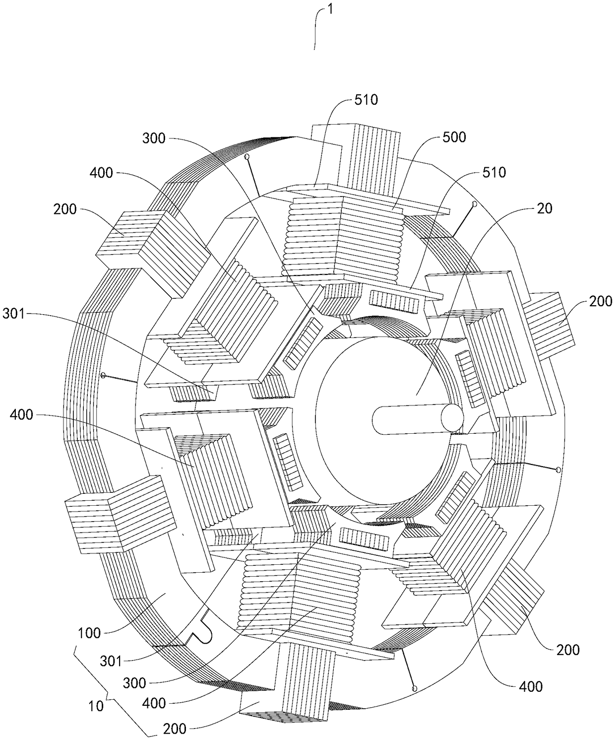
[0043] Such as figure 1 As shown, the motor 1 according to the embodiment of the present invention includes a stator 10 and a rotor 20 , the rotor 20 is rotatably fitted in the stator 10 , wherein the rotor 20 may be a permanent magnet ring rotor.

[0044] First, a stator 10 according to an embodiment of the present invention will be described with reference to the drawings.

[0045] Such as Figure 1-Figur...


PUM


Abstract

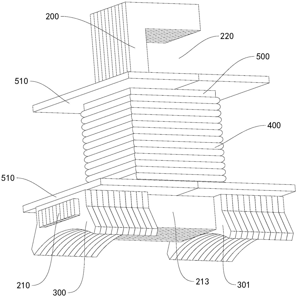
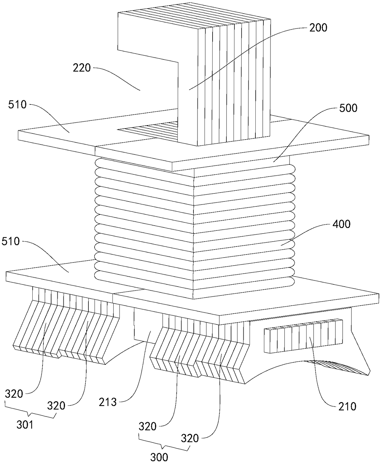
The invention discloses a stator and a motor with the same. The stator comprise a yoke part, a main gear part, a first gear boot part, a second gear boot part and a winding, wherein the yoke part is formed by laminating a plurality of yoke part punching sheets, the main gear part is formed by laminating a plurality of gear part punching sheets and is arranged on the yoke part in a clamping way, the gear part punching sheets are arranged in perpendicular to the yoke part punching sheets, an extending part is arranged at one end, facing an inner side in a radial direction of the yoke part, of the main gear part and extends along an axial direction of the yoke part, two ends of the extending part protrude out of the main gear part, the first gear boot part is formed by laminating a plurality of first gear boot punching sheets and is arranged at one end of the extending part in a clamping way, the first gear boot punching sheets are arranged in perpendicular to the gear part punching sheets, the second gear boot part is formed by laminating a plurality of second gear boot punching sheets and is arranged at the other end of the extending part in a clamping way, the second gear boot punching sheets are arranged in perpendicular to the gear part punching sheets, and the winding is wound around the main gear part. According to the stator disclosed by the embodiment of the invention, the axial size of each part can be independently set, so that the motor performance is favorably adjusted, and the stator is relatively low in cost.

Description

technical field [0001] The invention relates to the technical field of motors, in particular to a stator and a motor with the stator. Background technique [0002] In the motor in the related art, the stator yoke, teeth and tooth shoe are punched out as one piece, so the dimensions of the yoke, tooth and tooth shoe in the axial direction of the stator are consistent. For a unit surface area For a rotor with a weak magnetic field or a low rotation frequency, in order to save stator materials and improve its performance, the size of the yoke and teeth needs to be thinner and the area of ​​the tooth shoe larger, but affected by the radius of the inner circle of the stator, through Increasing the width of the tooth shoe to increase the area of ​​the tooth shoe has limited effect, and if the tooth shoe is expanded in the axial direction of the stator, the axial dimension of the yoke and the teeth will be lengthened, thereby increasing the material consumption of the iron core and...

Claims


Application Information

Patent Timeline
Patent Type & Authority Patents(China)
IPC IPC(8): H02K1/14H02K3/34
CPCH02K1/146H02K1/148H02K3/345H02K2213/03
Inventor 李春江陈金涛
Owner GUANGDONG WELLING ELECTRIC MACHINE MFG
Learn More