Automatic shaft sleeve assembly machine

A technology for assembling machines and shaft sleeves, which is applied in metal processing, metal processing equipment, manufacturing tools, etc., can solve problems such as low efficiency, low equipment utilization, and inability to realize continuous and uninterrupted assembly, and achieve convenient operation and structural Simplicity and the effect of improving equipment utilization

Inactive Publication Date: 2017-03-22
柳州市凯仕达汽车配件有限公司
View PDF5 Cites 18 Cited by
  • Summary
  • Abstract
  • Description
  • Claims
  • Application Information

AI Technical Summary

Problems solved by technology

[0003] Most of the existing shaft sleeve assembly equipment is semi-automatic. It is necessary to manually place the shaft on the carrier of the equipment, then manually put the shaft sleeve on the shaft, and then press the sleeve through the equipment. This method consumes a lot of time. Manpower, and frequent loading and unloading are required at the same time, and continuous and uninterrupted assembly cannot be achieved, so the efficiency of assembly is not high and the utilization rate of equipment is low

Method used


Image

  • Automatic shaft sleeve assembly machine
  • Automatic shaft sleeve assembly machine
  • Automatic shaft sleeve assembly machine

Examples


Embodiment Construction

[0031] In order to enable those skilled in the art to better understand the technical solution of the present invention, the present invention will be described in detail below in conjunction with the accompanying drawings. The description in this part is only exemplary and explanatory, and should not have any limiting effect on the protection scope of the present invention. .

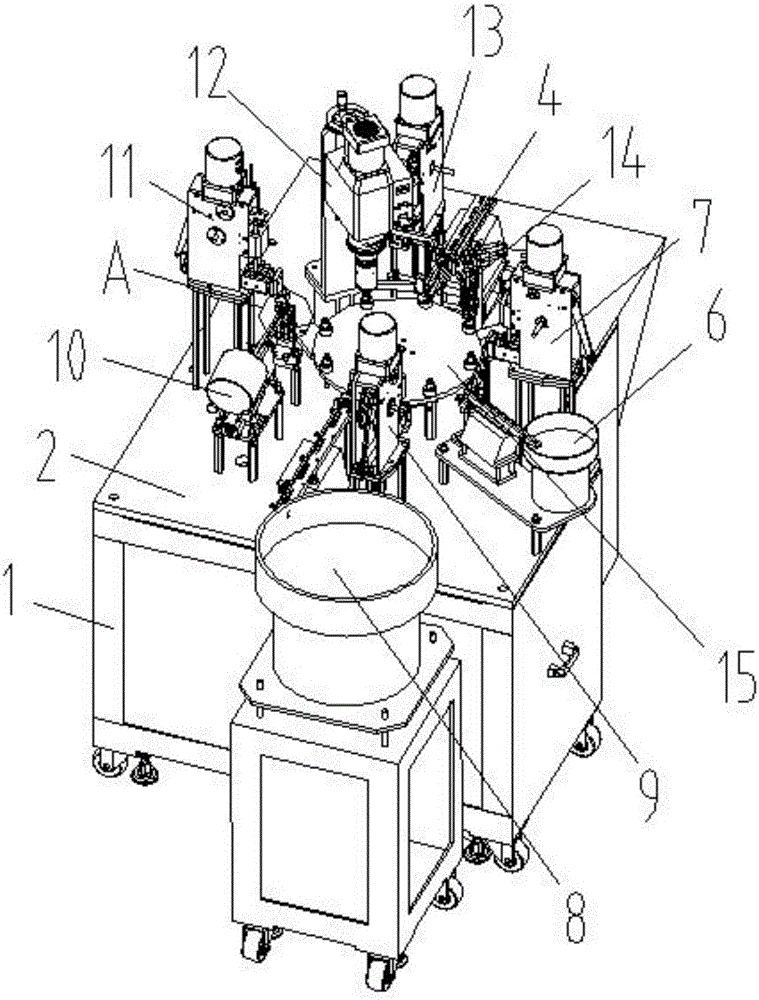
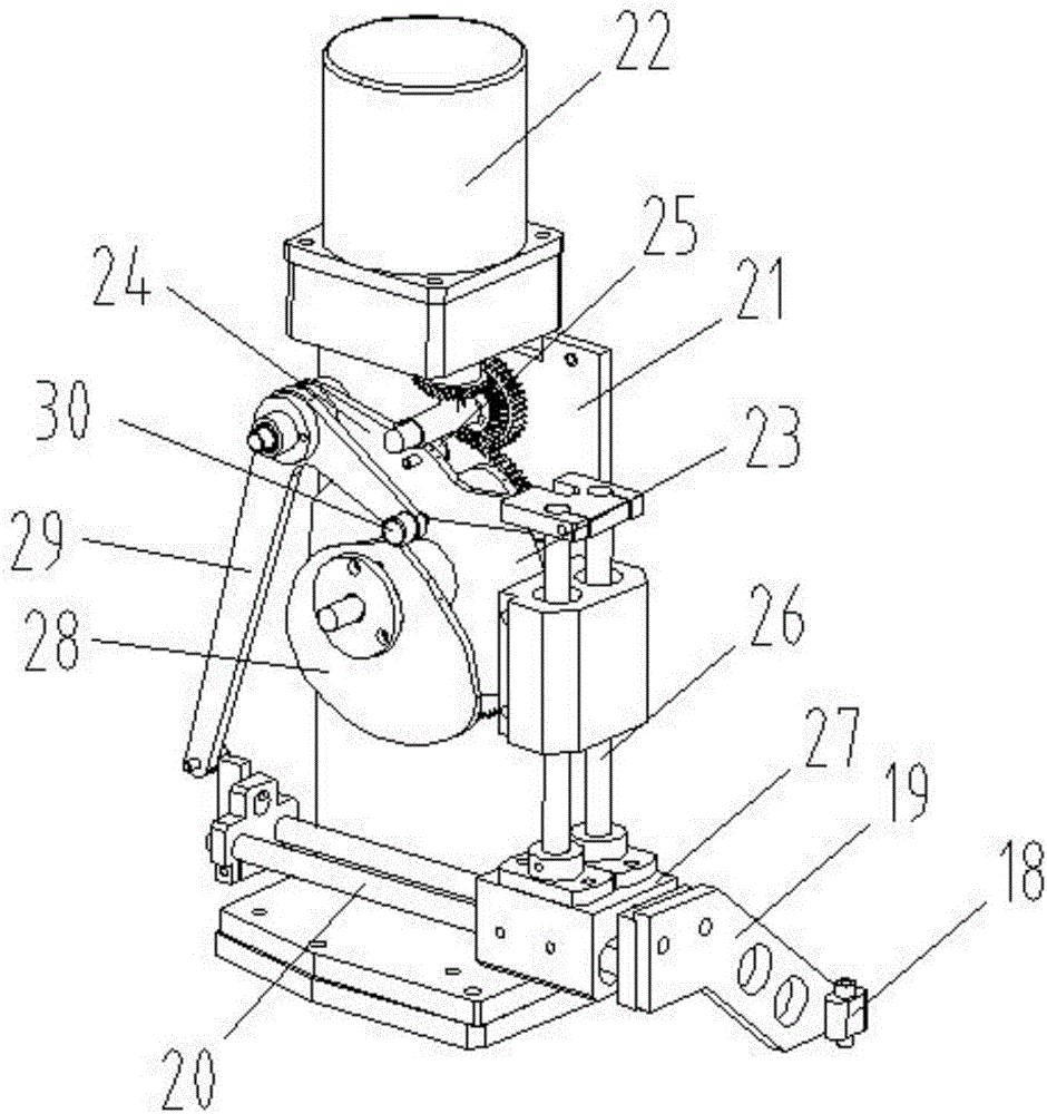
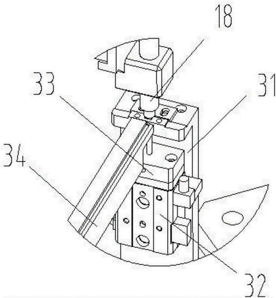
[0032] Such as Figure 1-Figure 6As shown, the specific structure of the present invention is: an automatic assembly machine for a shaft sleeve, which includes a frame 1 and a power distribution control box 2, the frame 1 is provided with a shaft sleeve installation turntable 15, and the shaft sleeve is installed The turntable 15 is connected to the shaft sleeve installation motor, and the shaft sleeve installation turntable 15 is evenly provided with loading holes that match the shafts, and the outer side is sequentially provided with shafts that match the loading holes and are connected to the power ...


PUM


Abstract

The invention relates to an automatic shaft sleeve assembly machine which comprises a rack and a power distribution control cabinet. The rack is provided with a shaft sleeve mounting rotary disc which is connected to a shaft sleeve mounting motor and uniformly provided with loading holes matched with shafts. A shaft feeding device, a shaft sleeve feeding device, a screw feeding device, a shaft sleeve pressing device and a shaft sleeve discharging device which are matched with the loading holes and connected to the power distribution control cabinet are sequentially arranged outside the shaft sleeve mounting rotary disc. According to the automatic shaft sleeve assembly machine, the shaft sleeve mounting rotary disc is arranged and uniformly provided with the loading holes matched with the shafts, the shaft feeding device, the shaft sleeve feeding device, the screw feeding device, the shaft sleeve pressing device and the shaft sleeve discharging device are sequentially arranged outside the shaft sleeve mounting rotary disc, integrated automatic continuous operation of shaft sleeves and screws is achieved, the shaft sleeve mounting efficiency is greatly improved, and meanwhile, the equipment utilization rate is increased.

Description

technical field [0001] The invention relates to the field of processing equipment for shaft parts, in particular to an automatic assembly machine for shaft sleeves. Background technique [0002] With the improvement of mechanization, the application of shaft parts is becoming more and more extensive. Mechanical shafts are used in almost all mechanical fields. When the shaft is applied, most of the shafts need to be sleeved on one end, so shaft sleeves are required. with equipment. [0003] Most of the existing shaft sleeve assembly equipment is semi-automatic. It is necessary to manually place the shaft on the carrier of the equipment, then manually put the shaft sleeve on the shaft, and then press the sleeve through the equipment. This method consumes a lot of time. Manpower and frequent loading and unloading are required, and continuous and uninterrupted assembly cannot be achieved, so the efficiency of assembly is not high, and the utilization rate of equipment is low. ...

Claims


Application Information

Patent Timeline
Patent Type & Authority Applications(China)
IPC IPC(8): B23P19/02
CPCB23P19/001B23P19/004B23P19/02
Inventor 曾波李川白云
Owner 柳州市凯仕达汽车配件有限公司
Why Eureka
Try Eureka