
Clamp of motor end cap

A technology of motor end cover and fixture, which is applied in the direction of clamping, manufacturing tools, metal processing machinery parts, etc., and can solve problems such as cumbersome operation, low clamping efficiency, and unstable quality

Inactive Publication Date: 2017-03-22
WUXI KAIHAN TECH
View PDF8 Cites 1 Cited by
  • Summary
  • Abstract
  • Description
  • Claims
  • Application Information

AI Technical Summary

Problems solved by technology

[0003] In view of the above problems, the present invention provides a clamp for the motor end cover, which can solve the technical problems of cumbersome operation, unstable quality and low clamping efficiency of traditional tooling

Method used


Image

  • Clamp of motor end cap
  • Clamp of motor end cap
  • Clamp of motor end cap

Examples


Embodiment Construction

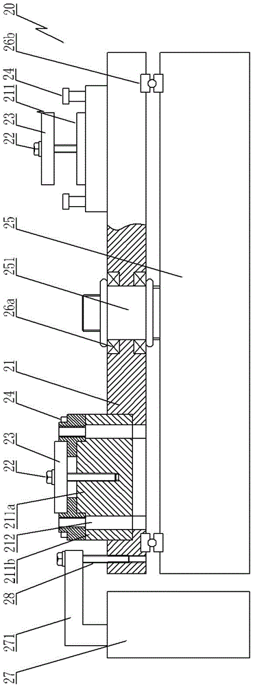
[0018] Such as Figure 1~Figure 3 As shown, the clamp 20 of the motor end cover includes a base plate 21, a turntable 25, a workpiece positioning mechanism, a workpiece pressing mechanism and a base plate positioning mechanism;

[0019] A rotating shaft 251 is fixed on the turntable 25, and the base plate is rotatably supported on the rotating shaft 251 through a roller bearing 26a. The upper end surface of the turntable and the lower end surface of the base plate are connected through a plane bearing 26b. Nuts are threaded at both ends of the rotating shaft axially, and the nuts are pressed into rollers. The inner ring of the sub-bearing;

[0020] The workpiece positioning mechanism includes a stepped positioning column 211 and a positioning pin 24,

[0021] A number of stepped positioning columns 211 are fixed on the base plate and distributed around the rotating shaft 251 in a circle. Each stepped positioning column 211 is embedded in the mounting hole of the base plate. T...


PUM


Abstract

The invention provides a clamp of a motor end cap, and can solve the technical problems that the traditional tool is tedious in operation, unstable in quality and low in clamping efficiency. According to the technical scheme, the clamp of the motor end cap comprises a bottom plate, and is characterized by further comprising a rotary table, a workpiece positioning mechanism, workpiece pressing mechanisms and a bottom plate positioning mechanism, wherein a rotating shaft is fixed on the rotary table; the bottom plate is rotatably supported on the rotating shaft; the workpiece positioning mechanism comprises a plurality of step-shaped positioning columns and positioning pins; the step-shaped positioning columns are fixed on the bottom plate and are distributed circumferentially around the rotating shaft; each step-shaped positioning column comprises an upper positioning part and a lower supporting part; each upper positioning part is matched with a corresponding bearing groove of the motor end cap; each lower supporting part is provided with a reference surface, a discharging hole and a workpiece positioning hole; each reference surface is attached to the lower end surface of the motor end cap; each discharging hole and the corresponding workpiece positioning hole are matched with a corresponding threaded hole and a corresponding unthreaded hole of the motor end cap; and the positioning pins are inserted in the workpiece positioning holes.

Description

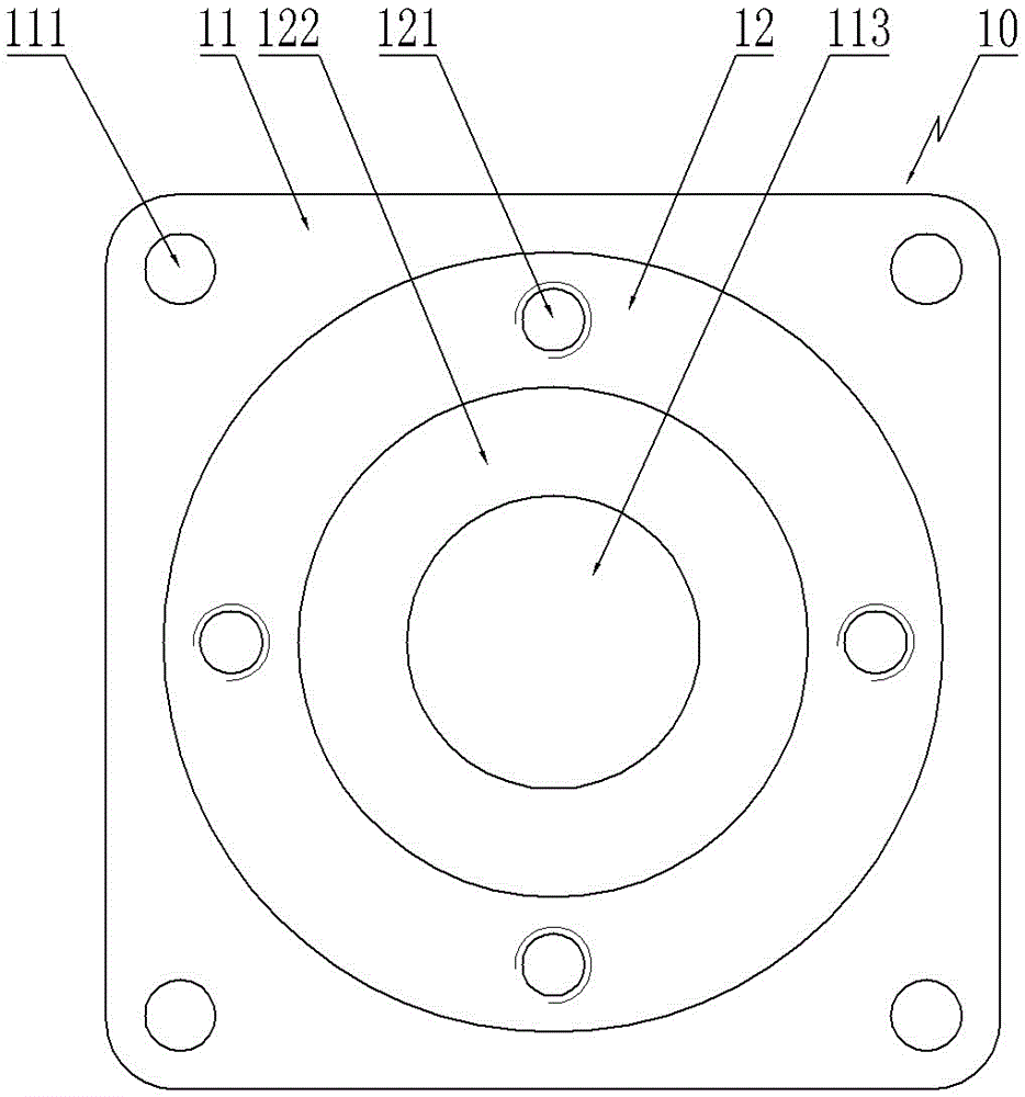
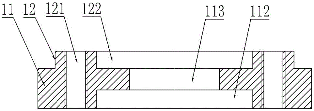
technical field [0001] The invention relates to the technical field of processing motor components; in particular, it relates to a clamp for a motor end cover. Background technique [0002] A kind of motor end cover 10, its structure is as figure 1 , figure 2 As shown, it includes a cover body 11 and an annular flange 12 arranged on the cover body 111. The edge of the cover body 11 is provided with a light hole 111 and a shaft hole 113 sequentially communicated with the groove 122 surrounded by the annular flange. And the bearing groove 112; the annular flange 12 is provided with a threaded hole 121 passing through the cover body 111 . Before machining the threaded holes, the motor end cover needs to be clamped on the tooling. The reliability and efficiency of the clamping directly affect the product quality and output. At present, the traditional tooling used is cumbersome to operate, unstable in quality, and low in clamping efficiency. Contents of the invention [0...

Claims


Application Information

Patent Timeline
IPC IPC(8): B23Q3/06
CPCB23Q3/062
Inventor 姚舜雄
Owner WUXI KAIHAN TECH
Learn More