
Peeling device for random number of cables

A cable and quantity technology, which is applied in the field of any number of cable peeling devices, can solve the problems of reducing recycling efficiency, increasing cost and operating procedures, and achieving the effect of shortening the spacing

Active Publication Date: 2021-03-26
山东城电电力工程有限公司
View PDF5 Cites 0 Cited by
  • Summary
  • Abstract
  • Description
  • Claims
  • Application Information

AI Technical Summary

Problems solved by technology

[0002] In the process of recycling power cables, it is necessary to perform sheath and core peeling operations. The inventor found that the invention patent is pending, and the patent number is CN201910450843.4- A power cable peeling and cutting device provides a device that can peel and cut power cables with different cross-sectional sizes and different numbers of wire cores, but the inventors have found that this invention requires multiple groups of wire core peeling supports 13, To meet the peeling operation of different wire cores, each wire core needs to be operated separately, which increases the cost and operation process, and the invention can only peel one cable, which reduces the recovery efficiency

Method used


Image

  • Peeling device for random number of cables
  • Peeling device for random number of cables
  • Peeling device for random number of cables

Examples


specific Embodiment approach 1

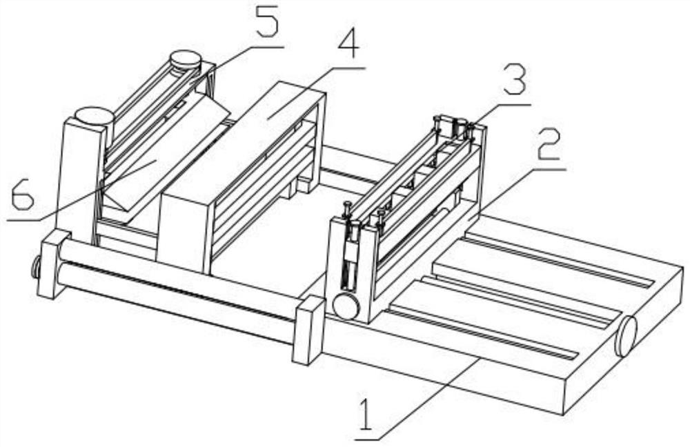
[0042] Combine below Figure 1-20 Describe this embodiment, a cable peeling device with any number, including a base 1, a cable positioning mechanism 2, a peeling mechanism 3, a core wire positioning mechanism 4, an adjustment mechanism 5 and a core wire peeling mechanism 6, the cable positioning The mechanism 2 is slidably installed in the groove provided on the base 1, the peeling mechanism 3 is fixedly installed on the cable positioning mechanism 2, the core wire positioning mechanism 4 is fixedly installed on the base 1, and the adjustment mechanism 5 is fixedly installed on the base 1. The wire peeling mechanism 6 is threadedly connected with the adjustment mechanism 5, and the core wire positioning mechanism 4 is fixedly connected with the core wire peeling mechanism 6.

specific Embodiment approach 2

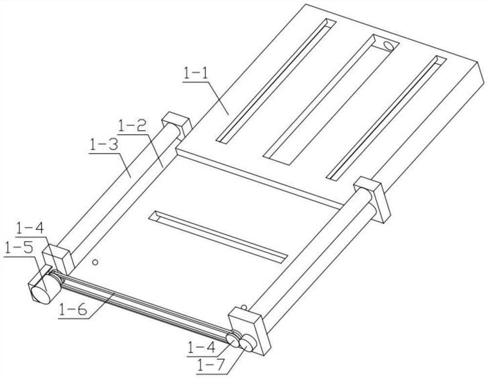
[0044] Combine below Figure 1-20 Describe this embodiment, this embodiment will further explain the first embodiment, the base 1 includes a base main body 1-1, a driving shaft 1-2, a driven shaft 1-3, a sprocket 1-4, and a driving motor 1 -5, chain 1-6, steering gear 1-7, the driven shaft 1-3 is installed in the groove provided on the base body 1-1 in rotation, and one end of the drive shaft 1-2 is installed in the base body 1-1 in rotation In the groove provided above, the other end of the drive shaft 1-2 passes through the base body 1-1 and is fixedly installed with a sprocket 1-4, and the other side of the sprocket 1-4 is fixedly installed on the drive motor 1-5. At the output end, the driving motor 1-5 is fixedly installed on the base body 1-1, the sprocket 1-4 is meshed with the chain 1-6, the steering gear 1-7 is meshed with the sprocket 1-4, and the steering gear 1-4 is meshed with the chain 1-6. 7 is fixedly installed on the drive shaft 1-2 on the other side.

specific Embodiment approach 3

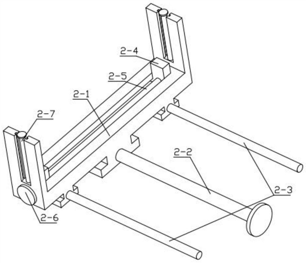
[0046] Combine below Figure 1-20 Describe this embodiment, this embodiment will further explain the second embodiment, the cable positioning mechanism 2 includes a U-shaped frame 2-1, a displacement threaded rod 2-2, a limit rod 2-3, an extrusion block 2- 4. Two-way threaded rod 2-5, rotating disk 2-6, vertical threaded rod 2-7, displacement threaded rod 2-2 is rotatably installed in the groove provided on the base body 1-1, and the limit rod 2-3 is fixed Installed on the base body 1-1, the displacement threaded rod 2-2 is threadedly connected with the U-shaped frame 2-1, and the U-shaped frame 2-1 is slidably installed in the groove provided on the base body 1-1, and the U-shaped frame 2 -1 is slidingly installed on the limit rod 2-3, and one end of the two-way threaded rod 2-5 is rotatably installed in the groove provided on the U-shaped frame 2-1, and the other end of the two-way threaded rod 2-5 passes through the U-shaped The frame 2-1 is fixedly installed with a rotati...


PUM


Abstract

The invention relates to the field of cable recycling machinery, in particular to a peeling device for random number of cables. The peeling device comprises a base, a cable positioning mechanism, a sheath removing mechanism, a core wire positioning mechanism, an adjusting mechanism and a core wire peeling mechanism, wherein the cable positioning mechanism is slidably mounted in a groove formed inthe base; the sheath removing mechanism is fixedly installed on the cable positioning mechanism, the core wire positioning mechanism is fixedly installed on the base, the adjusting mechanism is fixedly installed on the base, the core wire sheath removing mechanism is in threaded connection with the adjusting mechanism, and the core wire positioning mechanism is fixedly connected with the core wiresheath removing mechanism. The peeling device can operate a plurality of cables at the same time, can further meet the peeling operation of different numbers of cable cores, and can be adjusted according to the thickness of the sheath, thereby adapting to different sheath thicknesses.

Description

technical field [0001] The invention relates to the field of cable recovery machinery, in particular to a peeling device for any number of cables. Background technique [0002] In the process of recycling power cables, it is necessary to perform sheath and core peeling operations. The inventors found that the invention patent under examination, the patent number is CN201910450843.4, a power cable peeling and cutting device, which provides a device for different A device for peeling and cutting power cables with cross-sectional sizes and different numbers of wire cores, but the inventors have found that this invention requires multiple sets of wire core peeling supports 13 to meet the peeling operations of different wire core numbers, and each The wire cores are operated separately, which increases the manufacturing cost and operating procedures, and the invention can only perform the peeling operation on one cable, which reduces the recovery efficiency. Contents of the inv...

Claims


Application Information

Patent Timeline
Patent Type & Authority Applications(China)
IPC IPC(8): H01B15/00
CPCH01B15/006Y02W30/82
Inventor 李春雨
Owner 山东城电电力工程有限公司
Learn More