
Split type gantry plate-shaped material vertical corner clamping platform for water cutting

A split-type, gantry technology, applied in metal processing and other directions, can solve the problems of low efficiency of tooling, affecting the placement of plate materials, and unadjustable angles

Inactive Publication Date: 2020-04-14
ANHUI AOYU CNC TECH
View PDF8 Cites 1 Cited by
  • Summary
  • Abstract
  • Description
  • Claims
  • Application Information

AI Technical Summary

Problems solved by technology

[0002] Water cutting, also known as water jet, is high-pressure water jet cutting technology. It is a machine that uses high-pressure water jet cutting. Under the control of a computer, it can carve workpieces arbitrarily, and is less affected by the texture of the material because of its low cost and easy operation. The yield rate is high, and waterjet cutting is gradually becoming the mainstream cutting method in industrial cutting technology. In waterjet cutting operations, sometimes it is necessary to cut some plate-shaped materials, but most of the traditional plate-shaped material tooling components cannot be cut at any angle. Adjustment, under the barrier of components, will affect the placement of plate materials, resulting in low tooling efficiency. Therefore, we propose a split vertical corner clamping platform for plate materials for gantry water cutting to solve the above problems

Method used


Image

  • Split type gantry plate-shaped material vertical corner clamping platform for water cutting
  • Split type gantry plate-shaped material vertical corner clamping platform for water cutting
  • Split type gantry plate-shaped material vertical corner clamping platform for water cutting

Examples

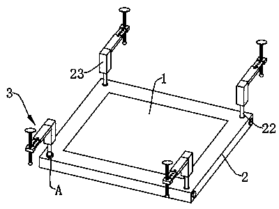
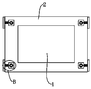
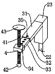

Embodiment Construction

[0024] The following will clearly and completely describe the technical solutions in the embodiments of the present invention with reference to the accompanying drawings in the embodiments of the present invention. Obviously, the described embodiments are only some, not all, embodiments of the present invention. Based on the embodiments of the present invention, all other embodiments obtained by persons of ordinary skill in the art without making creative efforts belong to the protection scope of the present invention.

[0025] see Figure 1-5 , the present invention provides a technical solution: a split-type gantry water cutting plate material vertical corner clamping platform, including a workbench 1, the outer wall of the workbench 1 is fixedly sleeved with a layer of back-shaped frame 2 with the same height The inside of the four corners of the back-shaped frame 2 is provided with a cavity 21, and the center of the bottom surface of the cavity 21 is rotated to be provided...


PUM


Abstract

The invention discloses a split type gantry plate-shaped material vertical corner clamping platform for water cutting. The clamping platform comprises a workbench, the outer wall of the workbench is fixedly sleeved with a concentric-square-shaped frame with the same height as the workbench; cavities are formed in four corners of the concentric-square-shaped frame; a rotating shaft is arranged on the bottom surface in each cavity; a part, extending to the upper side of the concentric-square-shaped frame, of the top end of each rotating shaft is provided with a holding block; an adjusting plateis arranged on the side wall of the upper end of each holding block; a mounting block is arranged at one end, away from the corresponding holding block, of each adjusting plate; a screw rod is inserted into each mounting block in a threaded manner; a pressing ball is arranged at the bottom end of each screw rod; the outer wall of the section, located in the corresponding cavity, of each rotating shaft is sleeved with a lantern ring; a plurality of annularly distributed flanges are fixedly arranged on the outer walls of the lantern rings; gaps between adjacent flanges is clamping slots; a spring groove is formed in the concentric-square-shaped frame on one side of each cavity; a sliding block is clamped in each spring groove in a sliding mode, a clamping block is fixedly arranged at one endof each sliding block, and the clamping blocks extend into the cavities to be movably clamped with the clamping grooves; a round rod is fixedly arranged on one face, back to the corresponding clamping block, of each sliding block, and the outer wall of each round rod is sleeved with a spring.

Description

technical field [0001] The invention relates to the technical field of plate-shaped material tooling, in particular to a split-type gantry water cutting plate-shaped material vertical corner clamping platform. Background technique [0002] Water cutting, also known as water jet, is high-pressure water jet cutting technology. It is a machine that uses high-pressure water jet cutting. Under the control of a computer, it can carve workpieces arbitrarily, and is less affected by the texture of the material because of its low cost and easy operation. The yield rate is high, and waterjet cutting is gradually becoming the mainstream cutting method in industrial cutting technology. In waterjet cutting operations, sometimes it is necessary to cut some plate-shaped materials, but most of the traditional plate-shaped material tooling components cannot be cut at any angle. Adjustment, under the barrier of components, will affect the placement of plate materials, resulting in low efficie...

Claims


Application Information

Patent Timeline
IPC IPC(8): B26D7/04B26F3/00
CPCB26D7/04B26F3/004
Inventor 徐昆
Owner ANHUI AOYU CNC TECH
Learn More