Automatic parallel movable template assembly, automatic parallel static template assembly, and emission device thereof

A technology of moving template and static template, applied in the field of automatic parallel moving template components, can solve the problems of poor parallelism of molds, non-parallel mold errors, and inability to completely close the molds, and achieve the effect of improving the quality of injection products.

Inactive Publication Date: 2017-03-22
PROWEAL COUNTER CORP
View PDF5 Cites 1 Cited by
  • Summary
  • Abstract
  • Description
  • Claims
  • Application Information

AI Technical Summary

Problems solved by technology

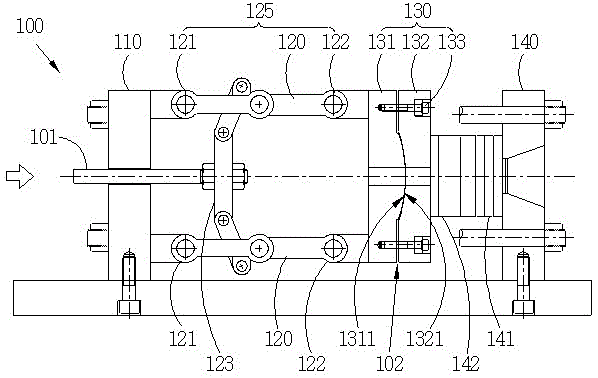
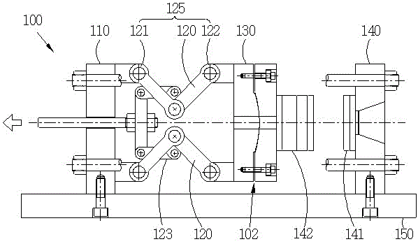
[0002] Generally speaking, the elbow of the elbow injection machine has several elbow arms, and each elbow arm has several joints; each joint is a shaft connection structure, and the components themselves have some errors; therefore, when these After the components are assembled into an elbow arm, due to the accumulation of errors of these components, the elbow arm will have a greater error, causing the moving template and the static template to be non-parallel
[0003] On the other hand, the male mold and the female mold are formed by stacking several mold pieces, and each mold piece itself has some errors; with the master model will have a larger error
[0004] From the above, it can be seen that whether it is the movable platen and the static platen of the elbow injection machine itself or the mold itself, there may be a large error of non-parallelism, resulting in poor parallelism between the molds; therefore, during the injection process, The mold cannot be completely closed, resulting in wear of the mold, damage to the machine itself, and quality problems such as burrs on the injected product.

Method used


Image

  • Automatic parallel movable template assembly, automatic parallel static template assembly, and emission device thereof
  • Automatic parallel movable template assembly, automatic parallel static template assembly, and emission device thereof
  • Automatic parallel movable template assembly, automatic parallel static template assembly, and emission device thereof

Examples


Embodiment Construction

[0016] In order for the benefit examiner to understand the features, content and advantages of the present invention and the effects it can achieve, the present invention will be described in detail as follows in conjunction with the accompanying drawings and in the form of embodiments. It is only for illustration and auxiliary description, not necessarily the true proportion and precise configuration of the present invention after implementation, so the scale and configuration relationship of the attached drawings should not be interpreted or limited to the scope of rights of the present invention in actual implementation.

[0017] The advantages, features and technical methods achieved by the present invention will be described in more detail with reference to the exemplary embodiments and the accompanying drawings to make it easier to understand, and the present invention may be implemented in different forms, so it should not be construed as being limited thereto The embodi...


PUM


Abstract

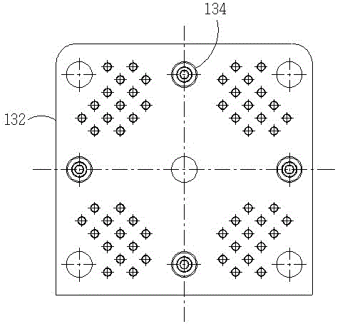
The invention discloses an automatic parallel movable template assembly, an automatic parallel static template assembly, and an emission device thereof. The automatic parallel movable template assembly comprises a movable template, a floating template, and a plurality of positioning screws. One end of the movable template is provided with a convex spherical surface (or a concave spherical surface), and the other end of the movable template is connected with second joints of various elbows in a pivoted. One end of the floating template is provided with a corresponding concave spherical surface (or a convex spherical surface), and is disposed on one end of the movable template. Various positioning screws pass through the floating template and the movable template. The automatic parallel static template assembly comprises a static template having one end provided with the convex spherical surface (or the concave spherical surface), and the floating template having the concave spherical surface (or the convex spherical surface) disposed on one end of the static template, and a plurality of positioning screws passing through the floating template and the static template.

Description

technical field [0001] The present invention relates to an automatic parallel motion template assembly, an automatic parallel static template assembly and an injection device thereof, in particular to a sliding adjustment between concave and convex spherical surfaces of the movable template assembly or the static template assembly, so that the male mold And the automatic parallel movement template assembly and its injection device that the mother mold can be parallel to each other. Background technique [0002] Generally speaking, the elbow of the elbow injection machine has several elbow arms, and each elbow arm has several joints; each joint is a shaft connection structure, and the components themselves have some errors; therefore, when these After the components are assembled into an elbow arm, due to the accumulation of errors of these components, the elbow arm will have a greater error, causing the moving template and the static template to be non-parallel. [0003] On...

Claims


Application Information

Patent Timeline
Patent Type & Authority Applications(China)
IPC IPC(8): B29C45/03B29C45/66
CPCB29C45/03B29C45/661B29C2045/033B29C2045/662
Inventor 李正隆
Owner PROWEAL COUNTER CORP
Why Eureka
Try Eureka