Rotor milling process

A rotor milling and rotor technology, which is applied in the manufacture of stator/rotor body, metal processing, milling machine equipment, etc., can solve problems such as low work efficiency and achieve the effect of improving transportation efficiency

Active Publication Date: 2021-06-18
重庆宝优机电有限公司
View PDF5 Cites 0 Cited by
  • Summary
  • Abstract
  • Description
  • Claims
  • Application Information

AI Technical Summary

Problems solved by technology

The current rotor processing technology is as follows: the operator takes the rotor to the milling machine, and then uses the milling cutter on the milling machine to mill the brushes of the rotor, and then the operator removes the rotor from the milling machine. In this way, on the one hand, not only the working efficiency On the other hand, it is dangerous for the operator to take the rotor directly

Method used


Image

  • Rotor milling process
  • Rotor milling process
  • Rotor milling process

Examples


Embodiment

[0040] A rotor milling process, using a rotor milling machine, comprising the steps of:

[0041] S1: Place the unmilled rotor on the transport mechanism, and transport the unmilled rotor to the grabbing position through the transport mechanism.

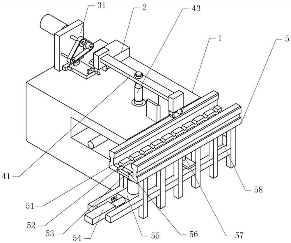
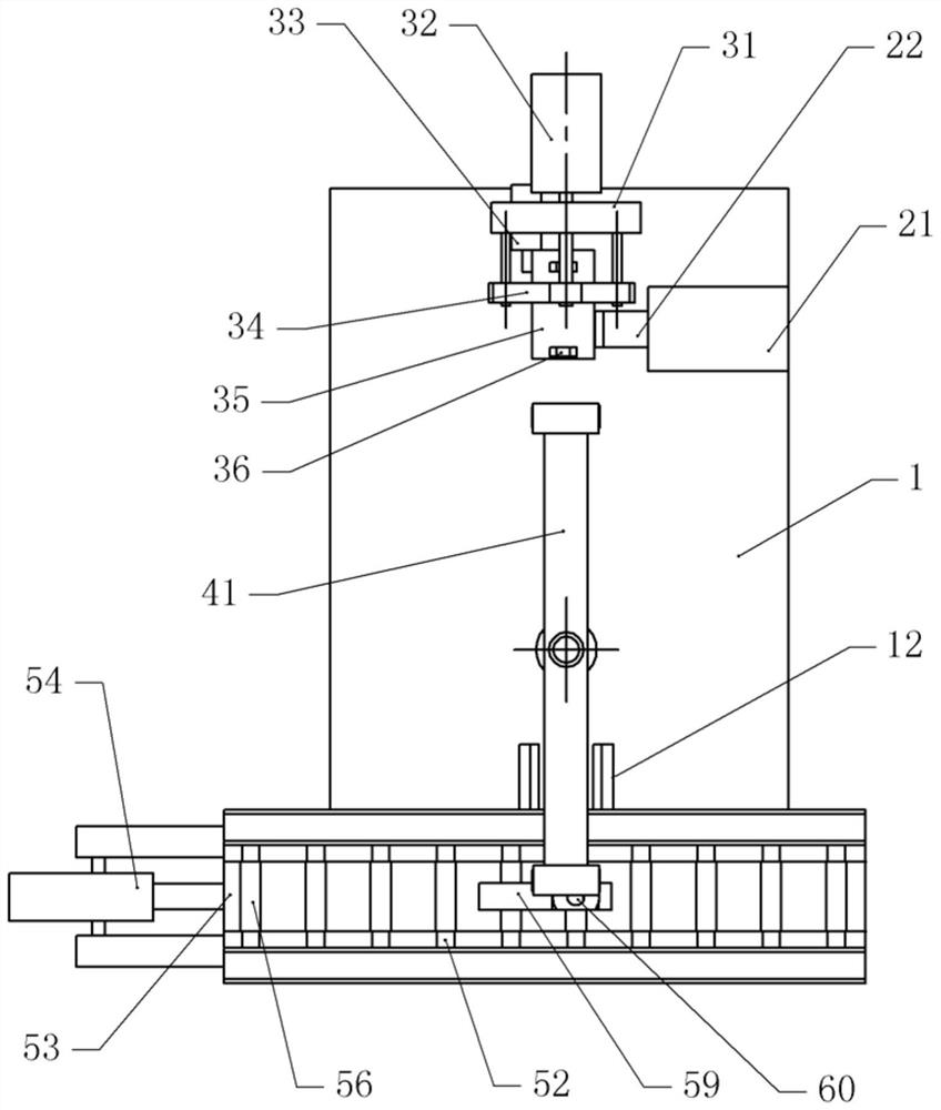
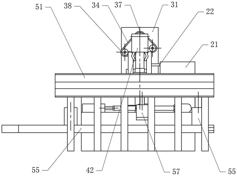
[0042] as attached figure 1 to attach image 3 As shown, the transportation mechanism 5 includes a frame, and the support plate 51 is fixed with bolts on both sides of the upper part of the frame, and the opposite side of the support plate 51 is provided with through grooves. Slot 52. In this embodiment, the longitudinal section of the limiting groove 52 is arc-shaped, and a lifting assembly is arranged between the supporting plates 51 on both sides. The lifting assembly includes a lifting plate 53 and several lifting cylinders 58. The lifting plate 53 is located on both sides Between the support plates 51, a plurality of support grooves 56 are formed on the lifting plate 53, and the longitudinal section of the support grooves 56 is...


PUM


Abstract

The invention relates to the technical field of rotor machining, and discloses a rotor milling process. The rotor milling process comprises the following steps that S1, a rotor which is not milled is placed on a conveying mechanism, and the rotor is conveyed to a grabbing position through the conveying mechanism; S2, after the rotor reaches the grabbing position, the rotor is jacked, and the rotor is grabbed through a grabbing mechanism; S3, the rotor is conveyed to a milling cutter mechanism through the grabbing mechanism, the position of a milling cutter mechanism is adjusted, then the rotor is placed on the milling cutter mechanism through the grabbing mechanism, and the position of the milling cutter mechanism is adjusted again till the milling cutter of the milling cutter mechanism abuts against an electric brush of the rotor; S4, the electric brush of the rotor is milled through the milling cutter mechanism until a finished rotor product is formed; and S5, the finished rotor and the non-milled rotor are synchronously grabbed through the grabbing mechanism, the step S3 is repeated after the grabbing mechanism grabs the non-milled rotor, and meanwhile, the grabbing mechanism transports the finished rotor to the conveying mechanism. The rotor milling process is simple, and the rotor machining safety is improved during machining.

Description

technical field [0001] The invention relates to the technical field of rotor processing, and specifically discloses a rotor milling process. Background technique [0002] The fixed part of the motor is called the stator (stator), on which a pair of stationary main poles of DC excitation are installed; the rotating part (rotor-rotor) is called the armature core, and the armature winding is installed on it. , After electrification, an induced electromotive force is generated, which acts as a rotating magnetic field to generate an electromagnetic torque for energy conversion. [0003] Before the rotor is installed, the brushes of the rotor need to be milled to make the brushes smoother and easier for the rotor to use. The current rotor processing technology is as follows: the operator takes the rotor to the milling machine, and then uses the milling cutter on the milling machine to mill the brushes of the rotor, and then the operator removes the rotor from the milling machine....

Claims


Application Information

Patent Timeline
Patent Type & Authority Applications(China)
IPC IPC(8): B23C3/00B23Q7/04H02K15/02
CPCB23C3/00B23Q7/04H02K15/02
Inventor 周建章周兵
Owner 重庆宝优机电有限公司
Why Eureka
Try Eureka