Lifting auxiliary device for electric equipment installation and using method thereof

A technology for power equipment and auxiliary devices, which is applied in the direction of hoisting devices, lifting frames, etc., and can solve the problems of inconvenient parts being transported to the lifting platform, manual adjustment, and the position of power equipment is not stable enough, etc.

Active Publication Date: 2021-11-26
JIANGSU ELECTRIC POWER CO
View PDF7 Cites 0 Cited by
  • Summary
  • Abstract
  • Description
  • Claims
  • Application Information

AI Technical Summary

Problems solved by technology

[0003] In the prior art, there are still the following disadvantages in the installation of large-scale power equipment: 1. It is necessary to use a crane to lift and adjust the equipment until it reaches the designated position, but the position of the power equipment is often not stable enough by means of hoisting. There are certain difficulties in installation; 2. It is impossible to adjust the angle of the power equipment. In a special installation site, it needs to be adjusted manually. 3. After the power equipment is lifted, it is inconvenient to transport the accessories to be installed to the lifting platform. , so in summary of the above-mentioned shortcomings, this technical solution proposes a lifting auxiliary device for electric equipment installation and its use method, which are used to solve the above-mentioned problems

Method used


Image

  • Lifting auxiliary device for electric equipment installation and using method thereof
  • Lifting auxiliary device for electric equipment installation and using method thereof
  • Lifting auxiliary device for electric equipment installation and using method thereof

Examples


Embodiment 1

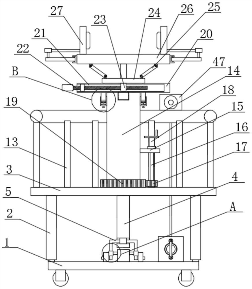
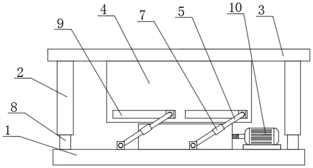
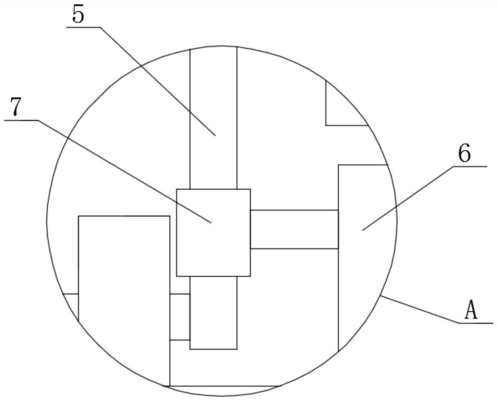
[0047] Embodiment one: if Figure 1-11 As shown, a lifting auxiliary device for electric equipment installation includes a mobile base 1, and limit posts 8 are fixedly installed on the four corners of the top of the mobile base 1, and the limit posts 8 are slidingly sleeved with limit covers 2, four The same support plate 3 is fixedly installed on the top of the limit cover 2, and the lifting plate 4 is fixedly installed on the bottom of the support plate 3, and two transmission holes 9 are symmetrically opened on the lifting plate 4, and the limit block is slidingly connected in the transmission hole 9 , and a U-shaped frame 5 is rotatably connected to the limiting block, and both ends of the two U-shaped frames 5 extend to the outside of the lifting plate 4 and are rotatably connected with the top of the mobile base 1, and the top of the mobile base 1 is fixedly installed with Drive motor 10, the output shaft of drive motor 10 is connected with two U-shaped frames 5 transmis...

Embodiment 2

[0061] Embodiment two: if Figure 12-15 As shown, a lifting auxiliary device for electric equipment installation, the difference between this embodiment and Embodiment 1 is that a limit plate 52 is fixedly installed on the top side of the mobile base 1, and the support shaft 48 penetrates the limit plate 52 and connects with the limit plate 52. The position plate 52 is rotatably connected, and one side of the limit plate 52 is fixedly equipped with a reset gear ring 49, and one end of the support shaft 48 is fixedly equipped with a mounting rod 50, and the mounting rod 50 is connected with two connecting shafts 51 for symmetrical rotation, and connected One end of the shaft 51 is fixedly equipped with a reset gear 54, and the two reset gears 54 are all meshed with the reset gear ring 49. The connecting shaft 51 is sleeved with a torsion spring 53, and the two ends of the torsion spring 53 are respectively connected to one end of the installation rod 50. side and one side of th...


PUM


Abstract

The invention discloses a lifting auxiliary device for electric equipment installation, which comprises a moving base, and limit columns are fixedly installed on the four corners of the top of the moving base, and the sliding sleeve on the limit column is provided with a limit cover. The top of the cover is fixedly installed with the same support plate, and the bottom of the support plate is fixedly installed with a lifting plate, and two transmission holes are symmetrically opened on the lifting plate, and a limit block is slidably connected in the drive hole, and the limit block U-shaped frames are rotatably connected to the upper part, and both ends of the two U-shaped frames extend to the outside of the lifting plate and are rotatably connected with the top of the mobile base. The present invention can realize clamping and fixing, lifting height and adjustment of electric equipment, so that good convenience can be provided when installing electric equipment, and accessories or fasteners can be transported upwards conveniently without repeated support plate Lifting is performed, so it has good practicality.

Description

technical field [0001] The invention relates to the technical field of electric equipment, in particular to a lifting auxiliary device for electric equipment installation and a usage method thereof. Background technique [0002] Power equipment mainly includes power generation equipment and power supply equipment. Power generation equipment is mainly power plant boilers, steam turbines, gas turbines, water turbines, generators, transformers, etc. Power supply equipment is mainly transmission lines of various voltage levels, transformers, contactors, etc. device and so on. [0003] In the prior art, there are still the following disadvantages in the installation of large-scale power equipment: 1. It is necessary to use a crane to lift and adjust the equipment until it reaches the designated position, but the position of the power equipment is often not stable enough by means of hoisting. There are certain difficulties in installation; 2. It is impossible to adjust the angle ...

Claims


Application Information

Patent Timeline
Patent Type & Authority Patents(China)
IPC IPC(8): B66F7/06B66F7/02B66F7/28
CPCB66F7/02B66F7/0608B66F7/0625B66F7/0641B66F7/28
Inventor 吴敬乐
Owner JIANGSU ELECTRIC POWER CO
Why Eureka
Try Eureka