Rear rear drive bus chassis drive train

A bus chassis and transmission system technology, applied in the direction of power devices, control devices, vehicle components, etc., can solve the problems of unreasonable distribution of front and rear axle loads, difficulties in rear engine placement, etc., to solve unreasonable distribution of axle loads and solve long-distance The effect of manipulating and simplifying the manipulating mechanism

Active Publication Date: 2018-10-09
JIANGSU RUIJIANG VEHICLE SYST CO LTD
View PDF7 Cites 0 Cited by
  • Summary
  • Abstract
  • Description
  • Claims
  • Application Information

AI Technical Summary

Problems solved by technology

[0004] The purpose of the present invention is to address the above-mentioned deficiencies in the prior art, and provide a rear-mounted rear-drive bus chassis drive train, which breaks the layout of the traditional bus power assembly by dividing and arranging the power assembly, and solves the difficulty of rear-mounting the engine. , The problem of unreasonable distribution of front and rear axle loads; at the same time, it solves the difficulty of long-distance operation of the transmission and simplifies the transmission control mechanism

Method used


Image

  • Rear rear drive bus chassis drive train
  • Rear rear drive bus chassis drive train
  • Rear rear drive bus chassis drive train

Examples


Embodiment Construction

[0025] Preferred embodiments of the present invention will be described in detail below in conjunction with the accompanying drawings.

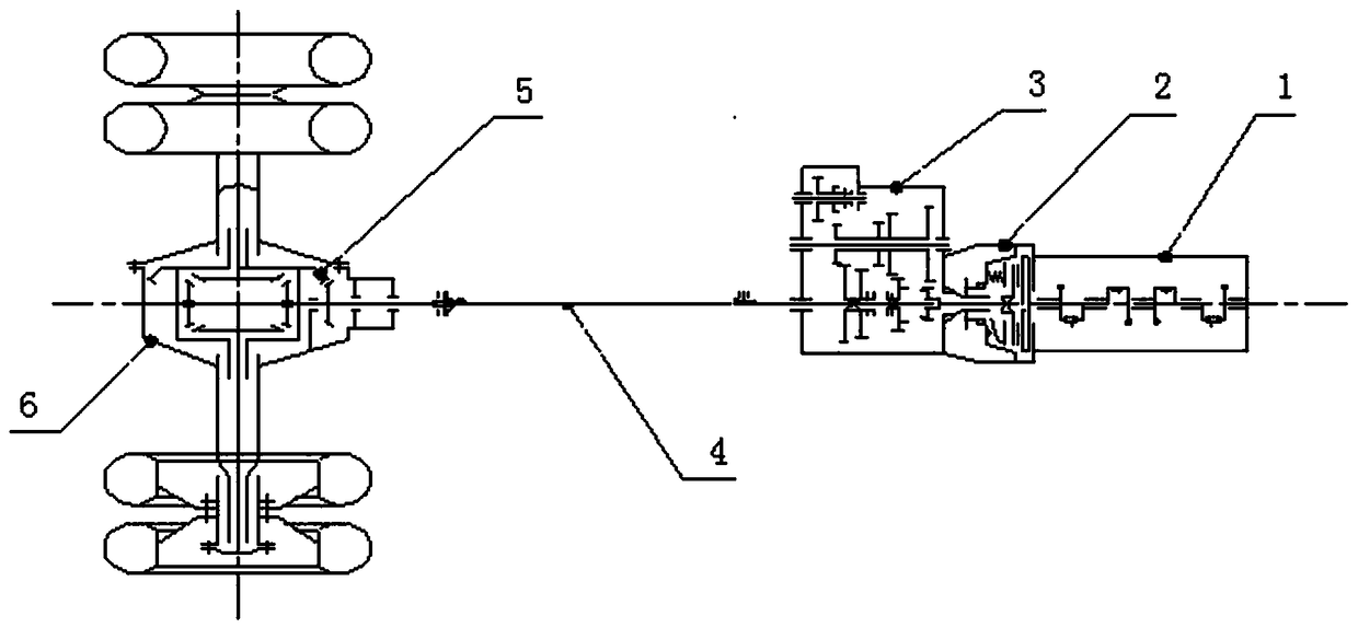
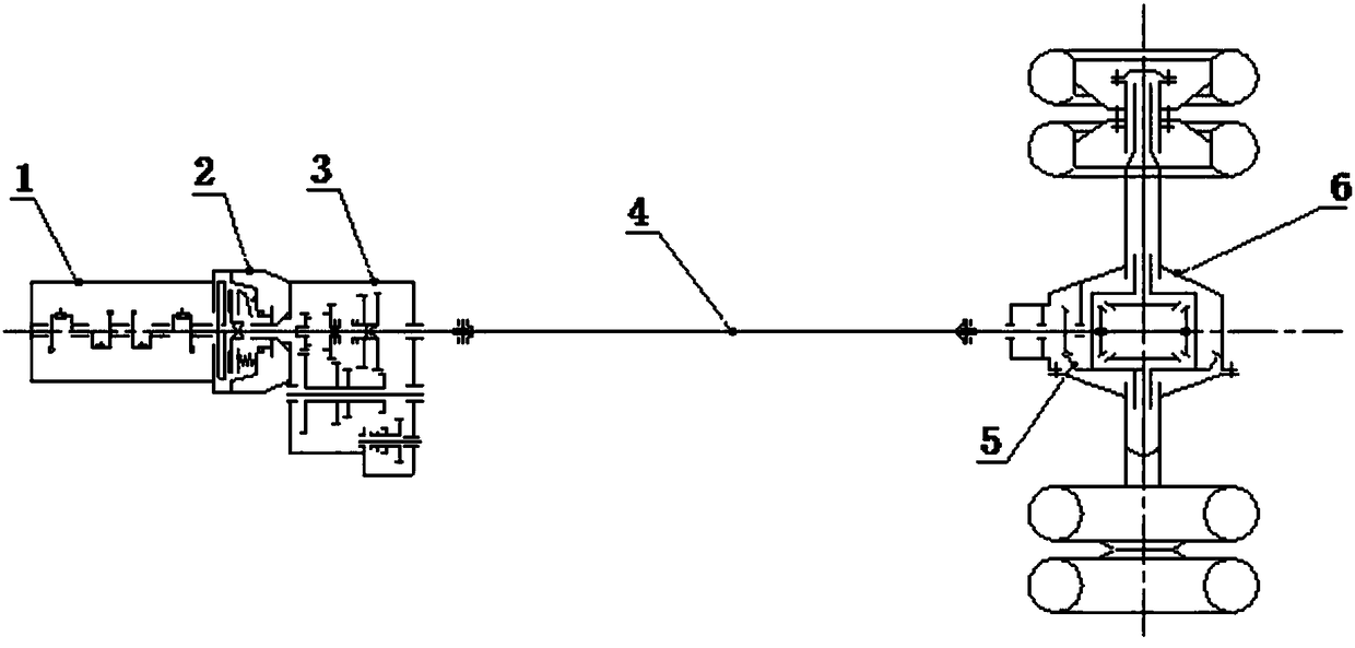
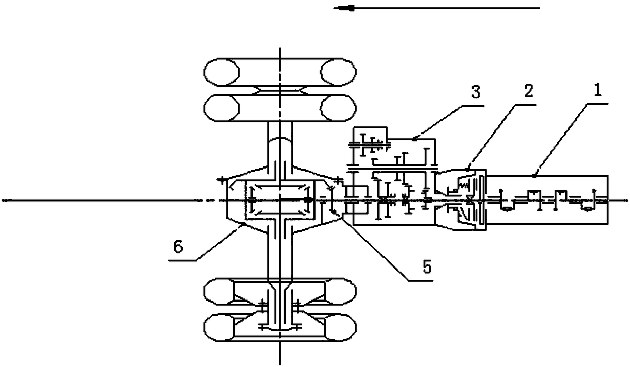
[0026] see figure 1 , the present invention discloses a chassis drive train of a rear-mounted rear-drive bus, comprising an engine 1, a clutch 2, a first speed reducer 10, a transmission 3, a first transmission shaft 8, a second transmission shaft 4, a third transmission shaft 7 and Rear axle, the rear axle 6 is provided with a transmission shaft support seat 9 and a final reducer 5; the engine 1 is connected to the input end of the clutch 2 and arranged behind the rear axle 6, and the output end of the clutch 2 is connected to the first The input end of the speed reducer 10 is connected, the output end of the first speed reducer 10 is connected with one end of the transmission shaft support base 9 through the first transmission shaft 8, and the other end of the transmission shaft support base 9 is connected with the The input shaft of the ...


PUM


Abstract

The invention discloses a rear-mounted rear-drive transmission system for a bus chassis. The rear-mounted rear-drive transmission system comprises an engine, a clutch, a first speed reducer, a speed changer, a first transmission shaft, a second transmission shaft, a third transmission shaft and a rear axle, wherein a transmission shaft supporting base and a main speed reducer are arranged on the rear axle; the engine is connected with the input end of the clutch and is arranged behind the rear axle; the output end of the clutch is connected with the input end of the first speed reducer; the output end of the first speed reducer is connected with one end of the transmission shaft supporting base through the first transmission shaft; the other end of the transmission shaft supporting base is connected with the input shaft of the speed changer located at the front end of the bus chassis through the second transmission shaft; the output shaft of the speed changer is connected with the input end of the main speed reducer through the third transmission shaft; and the output end of the main speed reducer is connected with the wheels through a suspension control arm. According to the rear-mounted rear-drive transmission system disclosed by the invention, the problems that an engine is mounted on the rear part of a shorter bus, the load distribution of a front axle and a rear axle is unreasonable and long-distance operation of the speed changer is difficult are solved, and the operating mechanism of the speed changer is simplified.

Description

technical field [0001] The invention belongs to the technical field of automobiles and relates to automobile power systems, in particular to a rear-mounted rear-drive passenger car chassis transmission system. Background technique [0002] At present, the layout of the rear-mounted bus chassis drive train is as follows: Figure 1 As shown, the power is transmitted from the engine to the transmission through the clutch, and then to the final drive through the transmission shaft. This traditional arrangement is often limited by the ratio of the rear overhang to the wheelbase for short-length passenger cars, which makes the distribution of front and rear axle loads unreasonable. Generally, the load on the front axle is too small. It is easy to cause the steering wheel to lose control, which is very unfavorable to car handling. In addition, it is almost impossible to arrange the rear suspension of a small passenger car (under 7 meters) with a traditional inline six-cylinder eng...

Claims


Application Information

Patent Timeline
Patent Type & Authority Patents(China)
IPC IPC(8): B60K17/02B60K17/04B60K17/08B60K5/02
CPCB60K5/02B60K17/02B60K17/04B60K17/08
Inventor 张龙利杨迪山罗千袁高翔
Owner JIANGSU RUIJIANG VEHICLE SYST CO LTD
Why Eureka
Try Eureka