

A space manipulator repetitive locking and releasing mechanism
A space manipulator, repeated locking technology, applied in the direction of motor vehicles, aerospace equipment, space vehicles, etc., can solve the problem of non-repeatable locking mechanism, mechanical arm impact, etc.
- Summary
- Abstract
- Description
- Claims
- Application Information
AI Technical Summary
Problems solved by technology
Method used
Image

Examples
Embodiment 1
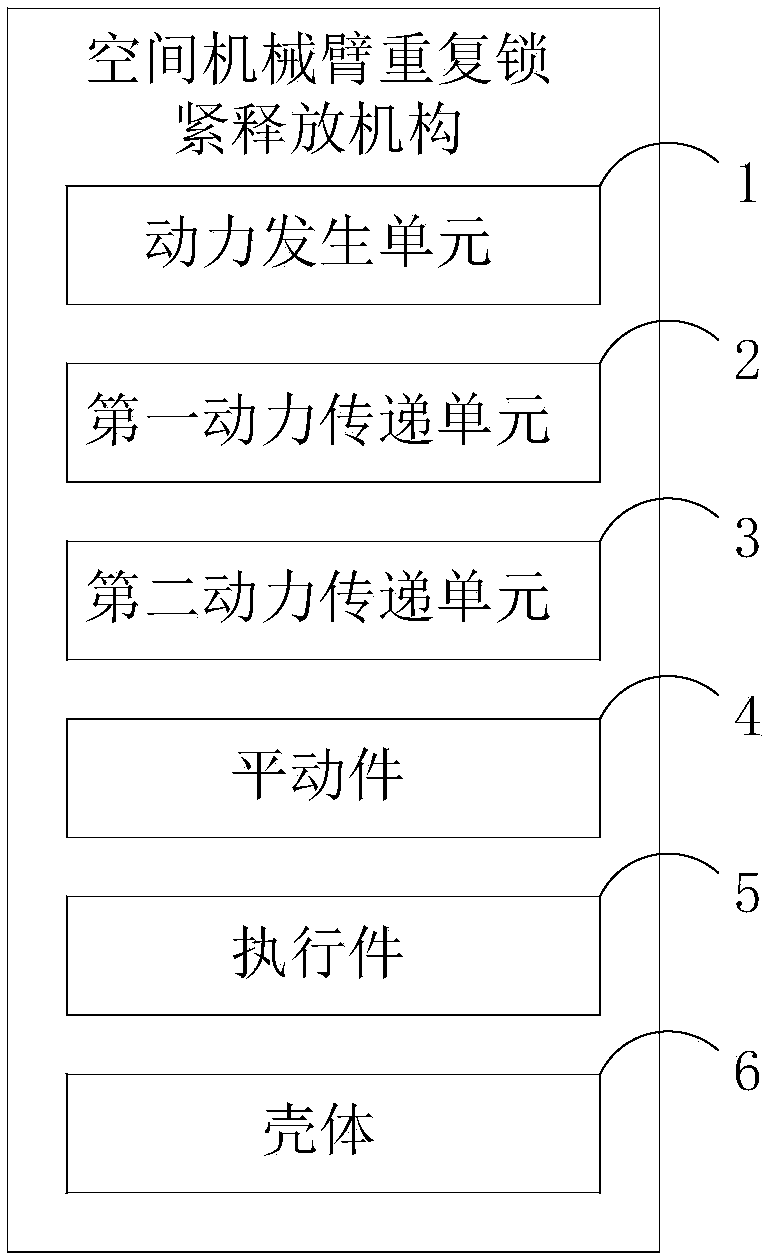
[0022] figure 1 It is a repetitive locking and releasing mechanism for a space manipulator, which includes a power generation unit 1, a first power transmission unit 2, a second power transmission unit 3, a translation piece 4, an actuator 5 and a housing 6;
[0023] A power generating unit 1, configured to generate rotational motion and transmit the rotational motion to the power transmission unit 1;
[0024] The first power transmission unit 2 is connected with the power generation unit 1, and is used to transmit the rotational motion generated by the power generation unit to the second power transmission unit 3;
[0025] The second power transmission unit 3 is connected with the first power transmission unit 2 and is used to convert the rotational motion into translational motion;
[0026] The translation member 4 is connected with the second power transmission unit 3, and is used for translation in the casing driven by the second power transmission unit 3;
[0027] The e...
Embodiment 2
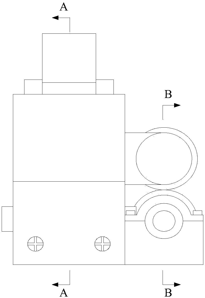
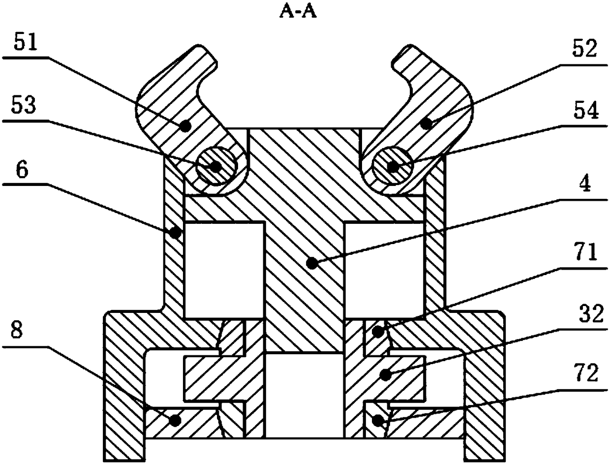
[0031] Such as Figure 2 to Figure 4 As shown, it is a repetitive locking and releasing mechanism of a space manipulator, which includes a driving motor 1, a transmission gear set: a cylindrical gear 21 and a cylindrical gear 22, a worm 31 and a worm wheel 32, a sliding block 4, a locking hook 51, a locking hook 52 and a shell body 6; the end of the output shaft of the driving motor 1 is fixedly connected with the housing 6 by screws, and the rotation of the driving motor 1 is transmitted to the cylindrical gear 22 meshing with it through the cylindrical gear 21 coaxial with the output shaft of the driving motor 1, wherein The spur gear 21 is transferred to the spur gear 22 and its connecting shaft is connected by keys respectively, the spur gear 22 is connected to the worm 31 by a key, and the worm 31 is connected to the housing 6 through deep groove ball bearings 91, 92 and glands 101, 102 respectively. The worm gear 32 is connected to the housing 6 through the support plate...
Embodiment 3
[0040] The difference of this embodiment is that the movement of the translator in the housing is a horizontal linear movement, which can be achieved by setting the axial direction of the output shaft of the drive motor to be vertical, The power is transmitted through the first power transmission unit, and the second power transmission unit realizes the conversion of the rotary motion into a horizontal linear motion, so that the locking part of the mechanical arm placed vertically can be locked.
PUM
 Abstract
Description
Claims
Application Information