Tensioning device capable of achieving automatic adjustment

A tensioning device and self-adjusting technology, applied in the textile field, can solve problems such as the reduction of the elastic coefficient, the tension provided by the cloth, and the fatigue failure of the spring.

Inactive Publication Date: 2017-03-22
赵旭
View PDF0 Cites 6 Cited by
  • Summary
  • Abstract
  • Description
  • Claims
  • Application Information

AI Technical Summary

Problems solved by technology

A more prominent disadvantage of this structure is that due to the repeated use of the spring, the spring will fail due to fatigue, so that its elastic coefficient will decrease, and eventually it will not be able to provide enough tension for the cloth, which will affect the density of the cloth after it is rolled.
[0004] In addition, the above-mentioned tensioning mechanism cannot provide stable tension for the cloth, because the friction force generated between the cloth and the drive roller is unstable (when the pressure between a pair of drive rollers increases, the friction between the cloth and the drive roller The friction force generated will increase, when the pressure between a pair of drive rollers decreases, or the drive roller is severely worn, the friction force generated between the cloth and the drive roller will decrease), and the size of the friction force will also increase Affects the tension of the cloth, for example, when the friction force decreases, the cloth begins to relax, so that the tension wheel starts to move toward the cloth, and the spring compression becomes smaller, so that the tension becomes smaller; conversely, when the friction force increases , so that the cloth starts to be tensioned, so that the tensioning wheel starts to move away from the cloth, and the compression degree of the spring increases, so that the tension increases
Unstable tension will also affect the density of the cloth after it is rolled

Method used


Image

  • Tensioning device capable of achieving automatic adjustment
  • Tensioning device capable of achieving automatic adjustment

Examples


Embodiment Construction

[0027] In order to enable those skilled in the art to better understand the technical solutions of the present invention, the present invention will be described in detail below in conjunction with the accompanying drawings and specific embodiments.

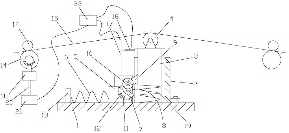
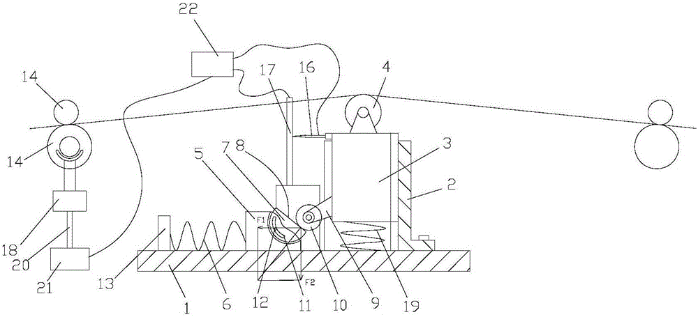
[0028] like figure 1 and figure 2 As shown, the embodiment of the present invention discloses a self-adjusting tensioning device for providing tension to the cloth 15 between two pairs of driving rollers 14 . The self-adjusting tensioning device specifically includes: a mounting base 1, a guide sleeve 2, a guide column 3, a tensioning wheel 4, a slider 5, a first spring 19, a second spring 6 and an adjustment mechanism. The mounting seat 1 is fixed on the overall equipment for conveying the cloth 15, and is located below the cloth 15 between two pairs of drive rollers 14; the guide sleeve 2 is fixed vertically on the mounting seat 1, and along the axial direction of the guide sleeve 2 A vertical groove is set on the cover wall...


PUM


Abstract

The invention discloses a tensioning device capable of achieving automatic adjustment. According to the tensioning device capable of achieving automatic adjustment, a sliding block is provided with an inclined plane with the tilting angle capable of being adjusted; and a guide post is provided with a guide part which stretches out of a guide sleeve and travels on the inclined plane, so that the inclined plane forces the guide part to drive the guide post to move vertically, and a tensioning wheel can be driven to move. By means of the tensioning device, the equivalent elastic coefficient of each spring can be changed by changing the tilting angle of the inclined plane, and therefore different tension ranges can be provided, namely the high range or the low range. Moreover, the influence on the elastic coefficients by spring failure can be compensated for by adjusting the tilting angle. Tension change caused by pressure variation between driving rollers can be adjusted through an adjusting mechanism, and accordingly the tension can be basically kept constant. In addition, the comovement relation between the movement directions of the tensioning wheel and the driving rollers is established through a sliding resistor, a controller and a servo motor, and thus the automatic adjustment function of the tensioning wheel is improved.

Description

technical field [0001] The invention relates to the technical field of textiles, in particular to an automatically adjustable tensioning device. Background technique [0002] In the field of textile technology, when the cloth is sorted into rolls, the cloth is generally conveyed on multiple pairs of drive rollers arranged at intervals. Specifically, the cloth is clamped between a pair of driving rollers, so that a certain frictional force is generated between the cloth and the driving rollers, so that the cloth is conveyed by the driving rollers. In order to make the cloth have a certain tension during the conveying process so that the cloth has a certain density after being rolled, usually, a tensioning mechanism is arranged between the two pairs of driving rollers, and the tensioning mechanism causes the cloth to generate a certain tension. [0003] In the prior art, the tensioning mechanism for tensioning the cloth includes a tensioning wheel for abutting against the clo...

Claims


Application Information

Patent Timeline
Patent Type & Authority Applications(China)
IPC IPC(8): B65H23/16
CPCB65H23/16
Inventor 赵旭
Owner 赵旭
Why Eureka
Try Eureka