
Yarn delivering wheel for knitting machine

A technology of feeding pulley and knitting machine, applied in the field of feeding pulley, can solve the problems of uneven yarn feeding tension, yarn breakage, hindering yarn feeding, etc., and achieves the effects of novel structure, constant tension and improved quality.

Inactive Publication Date: 2012-10-03
CIXI SUN TEXTILE SCI & TECH
View PDF5 Cites 1 Cited by
  • Summary
  • Abstract
  • Description
  • Claims
  • Application Information

AI Technical Summary

Problems solved by technology

For some multi-strand long-fiber yarns, since there are dozens of yarns, and even hundreds of filaments, the individual filaments of these yarns have low strength and are easy to break. Remains in the storage area of ​​the delivery wheel, hindering the delivery of the yarn, making the yarn feeding tension uneven and affecting the fabric quality of the knitting machine, and in severe cases, the yarn will be broken

Method used

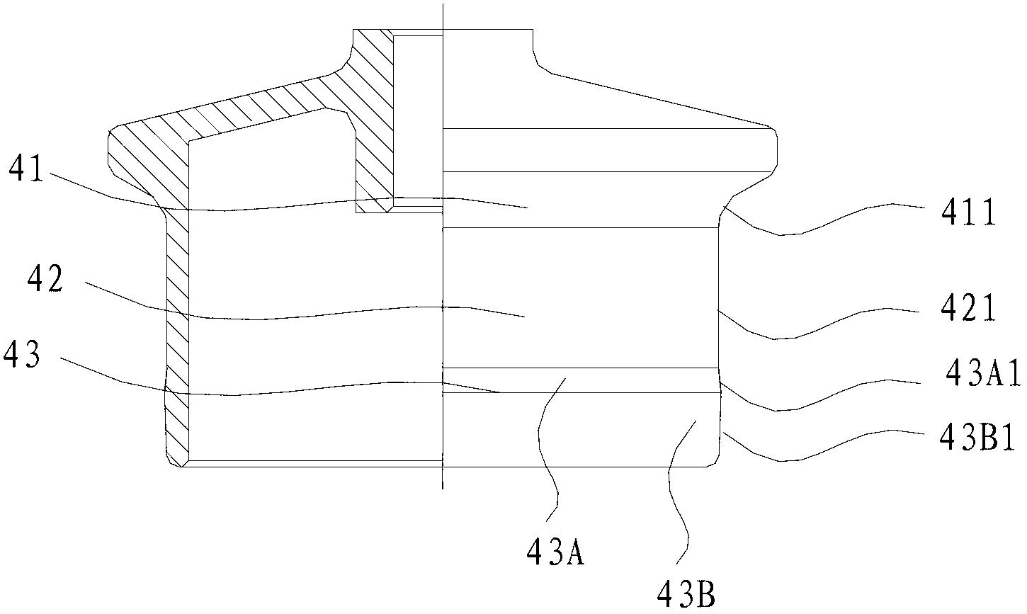

Image

  • Yarn delivering wheel for knitting machine
  • Yarn delivering wheel for knitting machine

Examples


Embodiment 1

[0014] like figure 1 The thread feeding wheel on the shown knitting machine, the thread feeding wheel includes from top to bottom successively a connected upper, lower, and lower yarn introduction cone 41, yarn storage cylinder 42 and waste silk exporter 43, and the waste silk is exported The body 43 includes a waste silk temporary storage cone 43A with a small top and a large bottom and a waste silk exporting cone 43B with a large top and a small bottom. The outer wall surface of the yarn introducing cone 41, that is, the yarn introducing area 411, is an arc surface inclined from outside to inside from top to bottom. The outer wall surface of the yarn storage cylinder 42 is the yarn storage area 421, and the outer wall surface is a plane. The outer wall surface of the waste silk temporary storage cone 43A and the waste silk exporting cone 43B is the waste silk exporting area, the outer wall surface of the waste silk temporary storage cone 43A is an upper slope 43A1, and the ...

Embodiment 2

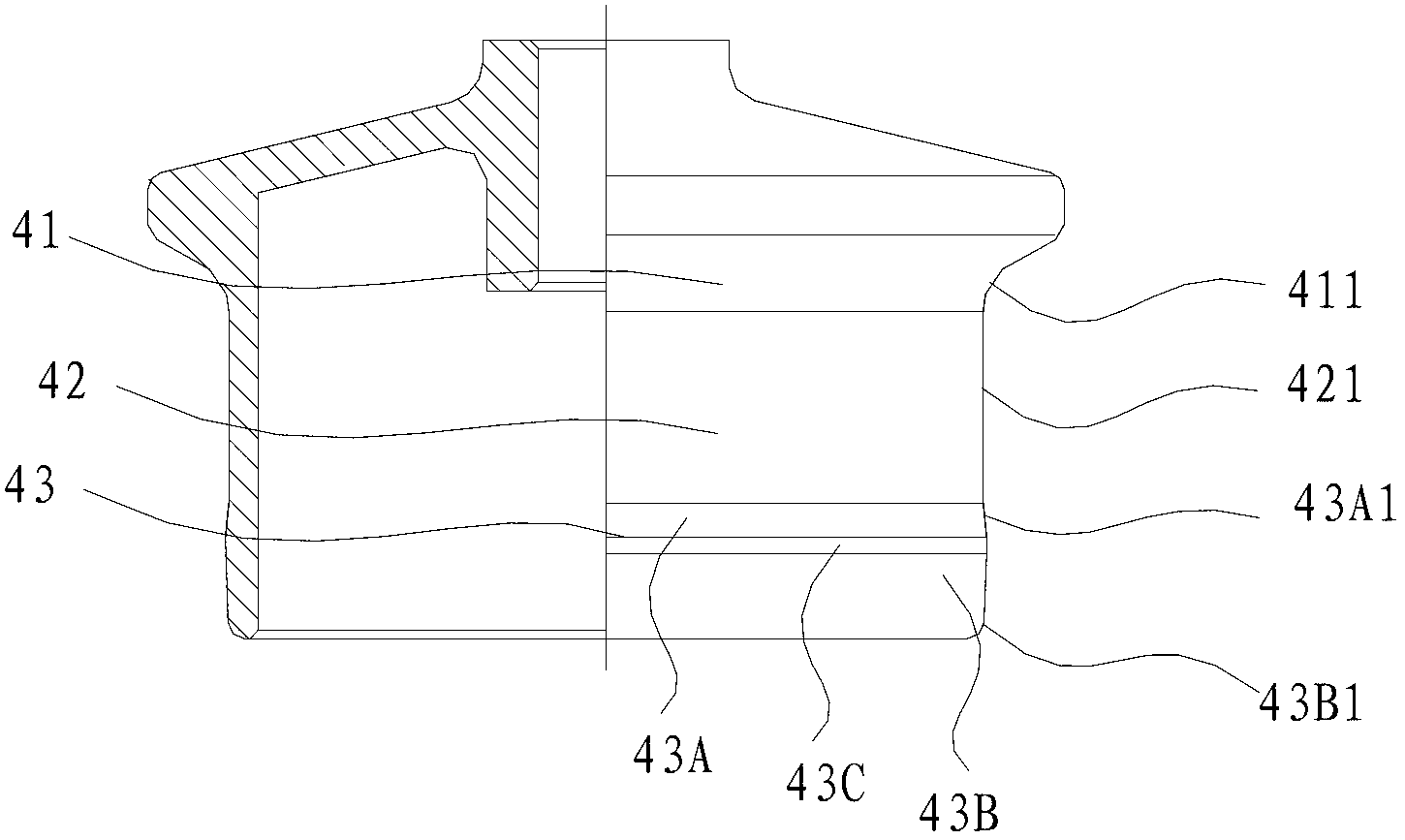
[0019] like figure 2 The structure and data of the wire feeding wheel on the knitting machine shown are the same as in Embodiment 1, the only difference is that the waste silk export body 43 also includes a waste silk transition cylinder 43C, and the waste silk temporary storage cone 43A and the waste silk export cone 43B pass through The waste silk transition cylinder 43C is connected, and the diameter of the waste silk transition cylinder 43C is the same as the diameter of the top of the waste silk export cone 43B.


PUM


Abstract

The invention relates to a knitting machine, particularly to a yarn delivering wheel for the knitting machine. The yarn delivering wheel sequentially comprises a yarn feeding cone, a yarn storage column and a waste silk leading-out body which are connected into a whole from top to bottom; the yarn feeding cone comprises a large upper part and a small lower part; the waste silk leading-out body comprises a waste silk temporary storage cone with a small upper part and a large lower part and a waste silk leading-out cone with a large upper part and a small lower part; the outside wall of the yarn feeding cone, namely a yarn feeding region, is an arc surface which inclines inwards from top to bottom; and an angle between an upper inclined surface and the outside wall of the yarn storage column is more than 150 degrees. The yarn delivering wheel for the knitting machine has the advantages of novel structure and capability of automatically removing residual waste silk, so that the tension force for delivering yarn for a knitting yarn delivering device keeps constant, therefore the quality of fabrics on the knitting machine is improved.

Description

technical field [0001] The invention relates to a knitting machine, in particular to a wire feeding wheel on the knitting machine. Background technique [0002] The thread feeding wheel on the existing knitting machine is mainly made of aluminum alloy as a whole, and consists of the upper yarn introduction area and the lower yarn storage area. In order to prevent the yarn from falling off, a Anti-snap shoulders. For some multi-strand long-fiber yarns, since there are dozens of yarns, and even hundreds of filaments, the individual filaments of these yarns have low strength and are easy to break. Remains in the storage area of ​​the delivery wheel, hindering the delivery of the yarn, making the yarn feeding tension uneven and affecting the fabric quality of the knitting machine, and in severe cases, the yarn will be broken. Contents of the invention [0003] The purpose of the present invention is to overcome the shortcomings of the above-mentioned existing yarn feeding wh...

Claims


Application Information

Patent Timeline
Patent Type & Authority Applications(China)
IPC IPC(8): D04B15/38
Inventor 高山
Owner CIXI SUN TEXTILE SCI & TECH
Learn More