Yarn conveying device used for knitting machine

A knitting machine and yarn feeding technology, applied in knitting, weft knitting, warp knitting and other directions, can solve the problems of unsatisfactory structure of the yarn feeder, yarn accumulation, winding, damage to the surface of the cloth, etc., achieving novel structure, The effect of reducing yarn breakage and clear cloth surface

Inactive Publication Date: 2018-12-11
伊婕
View PDF5 Cites 1 Cited by
  • Summary
  • Abstract
  • Description
  • Claims
  • Application Information

AI Technical Summary

Problems solved by technology

[0002] The yarn feeding device is an important part of the knitting machine. Whether the tension of the yarn feeding is constant will determine the quality of the knitted product. Since the diameter and strength of each yarn are small, when the yarn passes through the yarn feeding of the aforementioned prior art When using the machine, the unsatisfactory structure of the yarn feeder often causes the yarn to have uneven tension or thread breakage. After the thread breakage stops, the operator must deal with the thread breakage problem before continuing to weave the fabric. Since the general yarn feeding device cannot sense the required amount of yarn, yarn accumulation and entanglement often occur, which in turn causes the tension of the yarn itself to change and the surface of the fabric to be damaged.

Method used


Image

  • Yarn conveying device used for knitting machine
  • Yarn conveying device used for knitting machine

Examples


Embodiment Construction

[0017] The following will clearly and completely describe the technical solutions in the embodiments of the present invention with reference to the accompanying drawings in the embodiments of the present invention. Obviously, the described embodiments are only some, not all, embodiments of the present invention. Based on the embodiments of the present invention, all other embodiments obtained by persons of ordinary skill in the art without making creative efforts belong to the protection scope of the present invention.

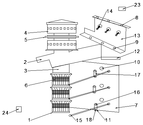
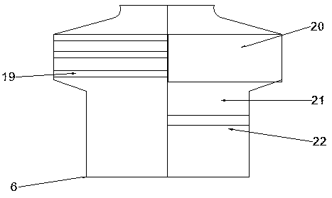
[0018] see Figure 1-2 , the present invention provides a technical solution: a yarn feeding device for a knitting machine, comprising a body 1, a fixing seat 2 is arranged on the body 1, a rotating shaft 3 is arranged in the middle of the fixing seat 2, and the rotating shaft 3 runs through up and down The fixed seat 2, the rotating shaft 3 above the fixed seat 2 is equipped with a driving pulley 4 and a clutch 5, the rotating shaft 3 below the fixed seat 2 i...


PUM


Abstract

The invention discloses a yarn conveying device used for a knitting machine. The device comprises a body. A fixing seat is arranged on the body. A rotary shaft is installed in the middle of the fixingseat. A main shaft vertically penetrates through the fixing seat. Driving belt pulleys and a clutch are arranged on the rotary shaft on the fixing seat. The rotary part at the bottom of the fixing seat is equipped with yarn conveying wheels. A yarn penetrating board is fixed below the fixing seat. The yarn penetrating board is vertically arranged besides the yarn conveying wheels. Third yarn guide eyes are arranged in the yarn penetrating board. The yarn penetrating board is equipped with a tension regulator. A yarn cleaning device is arranged at the lower end of the fixing seat. A wire rackis fixedly connected on the fixing seat. The wire rack is equipped with a micro-adjusting yarn-pressing device. The top end and the bottom end of the wire rack is equipped with multiple first yarn guide eyes and second yarn guide eyes. The yarn conveying device is clean in structure such that yarns have certain tension force and helps evidently reduce processing cost of broken yarns. The yarn conveying wheels can automatically clean residual filaments in order to increase quality of fabric on the knitting machine.

Description

technical field [0001] The invention relates to the technical field of knitting machines, in particular to a yarn feeding device for a knitting machine. Background technique [0002] The yarn feeding device is an important part of the knitting machine. Whether the tension of the yarn feeding is constant will determine the quality of the knitted product. Since the diameter and strength of each yarn are small, when the yarn passes through the yarn feeding of the aforementioned prior art When using the machine, the unsatisfactory structure of the yarn feeder often causes the yarn to have uneven tension or thread breakage. After the thread breakage stops, the operator must deal with the thread breakage problem before continuing to weave the fabric. Since the general yarn feeding device cannot sense the required amount of yarn, yarn accumulation and entanglement often occur, which in turn causes the tension of the yarn itself to change and the surface of the fabric to be damaged....

Claims


Application Information

Patent Timeline
Patent Type & Authority Applications(China)
IPC IPC(8): D04B15/54D04B15/44D04B27/10D04B27/12
CPCD04B15/54D04B15/44D04B27/10D04B27/12
Inventor 伊婕
Owner 伊婕
Why Eureka
Try Eureka