Floating breakwater with multiple columns of fence type wave stopping insertion plates and design method of floating breakwater

A technology of floating breakwaters and wave breakers, applied in the direction of breakwaters, jetties, embankments, etc., can solve the problems of rectangular pontoon section cost and mooring structure cost increase, reduce the mooring force of the mooring system, increase the anchoring force, etc., and achieve wave elimination The effect is remarkable, the cost is reduced, and the effect of increasing inertia

Active Publication Date: 2017-03-22
ZHEJIANG UNIV
View PDF4 Cites 24 Cited by
  • Summary
  • Abstract
  • Description
  • Claims
  • Application Information

AI Technical Summary

Problems solved by technology

At the same time, because the wave dissipation method of the rectangular pontoon breakwater is mainly based on reflected wave energy, the deeper the draft of the pontoon body, the better the effect of wave dissipation, but the anchor force will increase accordingly, and the cost of the section of the rectangular pontoon and the cost of the mooring structure will be correspondingly increased. will greatly increase
[0004] In the published related patents about the rectangular floating box-type floating breakwater, no attention has been paid to the technical scheme of using the restricted water body to increase the overall additi

Method used


Image

  • Floating breakwater with multiple columns of fence type wave stopping insertion plates and design method of floating breakwater
  • Floating breakwater with multiple columns of fence type wave stopping insertion plates and design method of floating breakwater
  • Floating breakwater with multiple columns of fence type wave stopping insertion plates and design method of floating breakwater

Examples


Embodiment Construction

[0049] The technical solutions of the present invention will be further described below, but the protection scope of the present invention is not limited to the implementation examples.

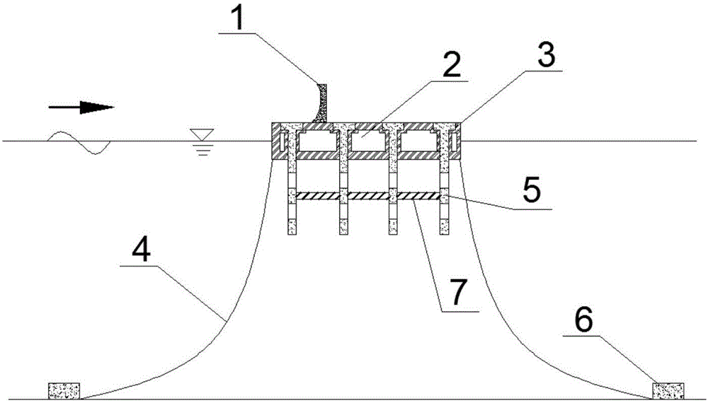
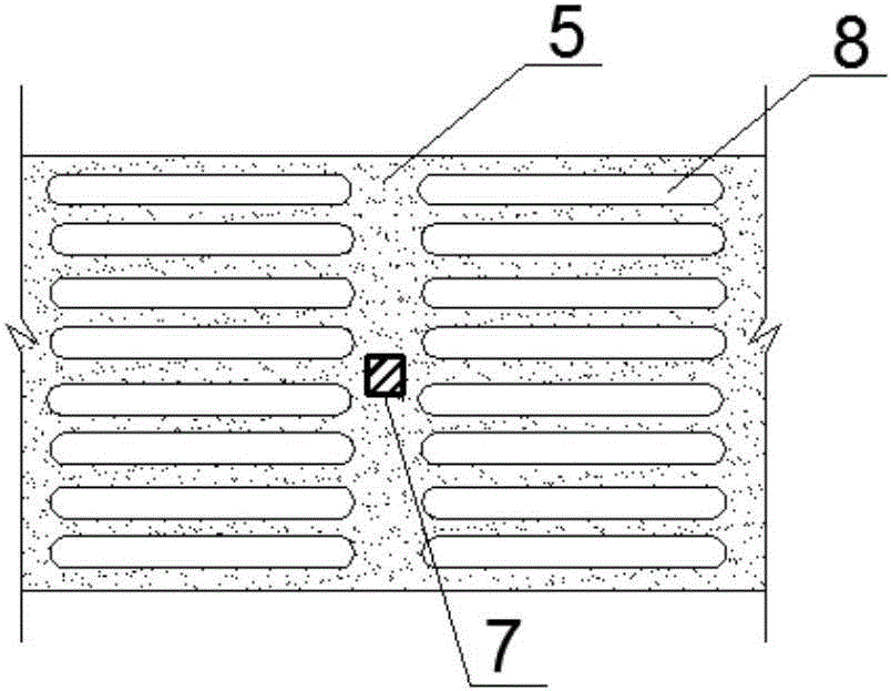
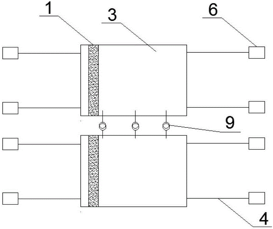
[0050] Working condition 1: (n=4, wave baffles are arranged in sequence) A certain project needs to build a section of floating breakwater in a certain sea area. The design wave height is 2.30m once in 50 years. Design of floating breakwaters with wave plates, such as image 3 As shown, the floating breakwater is composed of multiple breakwater structural units, such as figure 1 As shown, a single breakwater structural unit is composed of a wave wall 1, a rectangular buoy 3, a wave baffle 5, a support beam 7, an anchor cable 4, and a sinker 6, and each breakwater unit is connected by a hook 9. The structural unit of the breakwater takes the rectangular buoyant tank 3 as the main structure, and the inside is the hollow area 2 of the buoyant tank. The rectangular buoyant tank 3 is connected t...


PUM


Abstract

The invention discloses a floating breakwater with multiple columns of fence type wave stopping insertion plates and a design method of the floating breakwater, and belongs to the field of offshore engineering. The floating breakwater is composed of a plurality of breakwater units, a wave stopping wall is distributed on the wave facing side of the upper portion of a rectangular floating box of each breakwater unit, a plurality of T-shaped installation holes are reserved in the middle of each rectangular floating box, and the multiple columns of insertion type wave stopping plates are formed through embedding, fixing and joining. Each rectangular floating box is connected to a sinking block through an anchor cable and is then anchored in a design zone, and the breakwater units are in meshed connection through hooks. According to the floating breakwater, the water limiting effect is formed by the multiple columns of wave stopping plates, water bodies around the wave stopping insertion plates are used for increasing the additional mass of the overall floating breakwater, the inertia and the overall stability of the floating breakwater are improved, and motion of floating bodies is not limited by anchoring only; and meanwhile, the fence type wave stopping insertion plates give consideration to energy transformation of reflection energy dissipation and turbulent fluctuation energy dissipation on the aspect of energy dissipation, and the wave dissipation effect of the breakwater can be obviously improved.

Description

technical field [0001] The invention relates to a novel floating breakwater and a design method thereof, in particular to a floating breakwater with multi-row fence-type wave-retaining inserts and a design method thereof. Background technique [0002] As a traditional engineering structure, the breakwater mainly plays the role of reducing the wave transmission coefficient, improving the mooring stability of the harbor basin, and protecting designated water areas. Floating breakwaters are widely used in deep water areas due to their low construction cost, not being restricted by the geological conditions of the seabed, rapid construction, and convenient demolition. [0003] Due to its simple structure, strong reliability, and easy maintenance, the rectangular floating box-type floating breakwater has become the main structural type of floating breakwater used in engineering. Rectangular pontoon type floating breakwater is usually composed of rectangular pontoon body and moor...

Claims


Application Information

Patent Timeline
IPC IPC(8): E02B3/06
CPCE02B3/062
Inventor 何方冷杰
Owner ZHEJIANG UNIV
Why Eureka
Try Eureka