Asymmetric double-buoy floating breakwater

A floating breakwater and double buoy technology, applied in the directions of breakwaters, jetties, embankments, etc., can solve the problems of unsatisfactory wave elimination effect of single floating box floating breakwater, achieve simple structure, increase wave absorption capacity, reduce The effect of project cost

Pending Publication Date: 2019-06-21
OCEAN UNIV OF CHINA
View PDF0 Cites 3 Cited by
  • Summary
  • Abstract
  • Description
  • Claims
  • Application Information

AI Technical Summary

Problems solved by technology

However, the wave dissipation effect of single pontoon type floating breakwater is often unsatisfactory, especially for longer period waves. In order to overcome this defect, it is necessary to study multi-pontoon type floating breakwater

Method used


Image

  • Asymmetric double-buoy floating breakwater
  • Asymmetric double-buoy floating breakwater
  • Asymmetric double-buoy floating breakwater

Examples


Embodiment 1

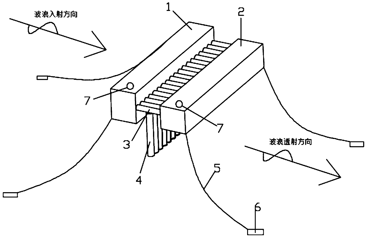
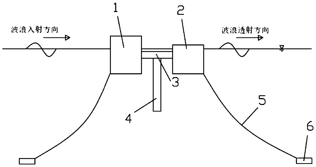
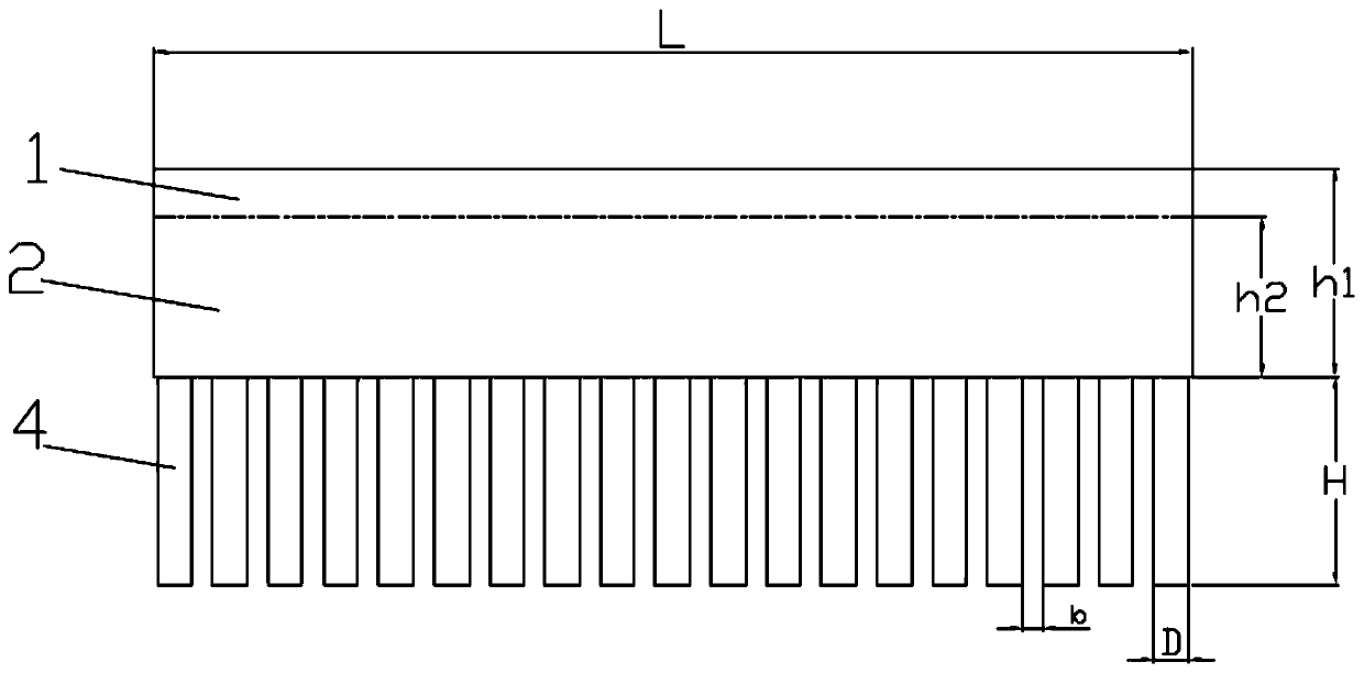
[0039] The present invention provides an asymmetric double buoy type floating breakwater, which includes a front buoy 1, a rear buoy 2, a connecting piece 3 and an energy dissipating piece 4, the front buoy 1 and the rear buoy 2 are fixedly connected as a whole through the connecting piece 3; The energy dissipation element 4 is vertically arranged on the connection element 3, and the energy dissipation element 4 is fixedly connected with the connection element 3. The energy dissipation element 4 is used to disturb the wave movement, and the energy dissipation element 4 dissipates the energy of the wave through friction and turbulence between the water body and the water body. surface energy.

[0040] The mooring device includes an anchor chain 5 and a sinker 6, one end of the anchor chain 5 is fixedly connected to the sinker 6, the other end of the anchor chain 5 is fixedly connected to the front buoy 1 and the rear buoy 2 respectively, and the anchor chain arranged on the same...

Embodiment 2

[0051] This embodiment is slightly modified on the basis of the above-mentioned embodiment 1, such as Figure 5 As shown, the anti-collision device 8 is symmetrically arranged on the outside of the front buoy 1 and the rear buoy 2. The anti-collision device 8 includes an anti-corrosion layer 801, a front stressed steel plate layer 802, a stressed cavity 803, a spring 804, and a rear stressed steel plate Layer 805, flexible buffer layer 806.

[0052] Specifically, the internal structure of the anti-collision device 8 is as follows: Image 6 As shown, the anti-corrosion layer 801 is arranged on the outermost side of the anti-collision device 8, that is, the anti-corrosion layer 801 is arranged on the outer side of the front stressed steel plate layer 802 and the upper side and the lower side of the stressed chamber 803 to prevent seawater from corroding, and the front stressed steel plate The space between the layer 802 and the rear stressed steel plate layer 805 constitutes a ...


PUM


Abstract

The invention relates to the technical field of coastal engineering, in particular to an asymmetric double-buoy floating breakwater. The breakwater comprises a front buoy, a rear buoy, a connecting piece and energy dissipation pieces, the front buoy and the rear buoy are fixedly connected with two ends of the connecting piece respectively, the energy dissipation pieces used for disturbing wave motion are perpendicularly arranged on the connecting piece, the wave dissipation vertical water depth range is increased through the energy dissipation pieces, and surface energy of waves is dissipatedthrough friction and turbulence between the energy dissipation pieces and a water body. The energy dissipation pieces are stainless steel pipes or glass fiber reinforced plastic, and the buoy is madeof concrete or glass fiber reinforced plastic. According to the design, an asymmetric double-buoy form is adopted, the relative width of the floating breakwater is increased, the construction cost isreduced, meanwhile, waves are reflected through the front buoy, broken in the middle gaps and reduced again through the rear buoy, the multiple wave reduction effect is achieved, the wave absorbing capacity is remarkably improved, and particularly the long-period wave reduction effect is improved.

Description

technical field [0001] The invention relates to the technical field of coastal engineering, in particular to an asymmetrical double buoy type floating breakwater. Background technique [0002] The structure of breakwaters can generally be divided into two types: heavy and light. Heavy breakwaters are traditional and commonly used types of breakwaters, including slope embankments, straight wall embankments, and composite embankments. Light breakwaters have been developed in recent decades. Based on the characteristics of the surface layer and combined with the special needs of the project, various light breakwaters have been researched, such as air-permeable dikes, floating dikes, jet dikes and jet dikes. [0003] Compared with traditional breakwaters, floating breakwaters can adapt to conditions such as large water depths, weak foundations, large tidal ranges, and introduced water exchange, and have broad prospects in many fields such as port coastal engineering, marine engi...

Claims


Application Information

Patent Timeline
IPC IPC(8): E02B3/06
CPCY02A10/11
Inventor 刘勇梁家铭刘晓何舒玥王晓亮胡佳明
Owner OCEAN UNIV OF CHINA
Why Eureka
Try Eureka