
a floating breakwater

A technology of floating breakwaters and floating bodies, which is applied in the direction of breakwaters, jetties, embankments, etc. It can solve the problems of box or floating row damage, difficult maintenance and replacement, complex equipment, etc., and achieves convenient maintenance, good wave dissipation effect, and reduced waves Effect of Transmission Coefficient

Active Publication Date: 2018-09-11
CCCC FHDI ENG +1
View PDF9 Cites 0 Cited by
  • Summary
  • Abstract
  • Description
  • Claims
  • Application Information

AI Technical Summary

Problems solved by technology

[0004] The wave dissipation effect of the floating breakwater is mainly related to W / L (width of floating body / wavelength) and h / d (height of floating body / water depth). Therefore, for different sea areas, the structural size of the floating breakwater needs to be designed according to the specific wave conditions on site. Floating breakwaters of one structural size can only be used for a single wave condition, resulting in multiple repeated designs for similar projects
At the same time, due to the complex anchoring equipment and poor reliability of the floating breakwater, after a period of wave action, the box or floating row will be damaged due to mutual collision, and the structure of the above floating breakwater also has the problem of difficult maintenance and replacement.

Method used


Image

  • a floating breakwater
  • a floating breakwater
  • a floating breakwater

Examples


Embodiment Construction

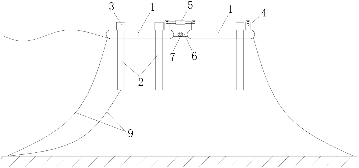
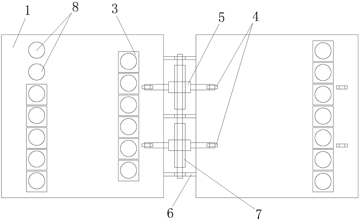
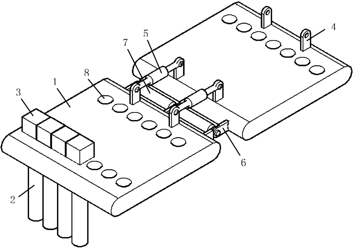
[0019] In this example, refer to figure 1 , figure 2 and image 3 , the floating breakwater includes several floating bodies 1, the floating bodies 1 are installed through the anchoring structure 9, there are several pipe holes 8 in the floating body 1, and the wave-dissipating steel pipes 2 are arranged in the pipe holes 8; the adjacent floating bodies 1 are connected to each other .

[0020] The wave-dissipating steel pipe 2 is a closed structure, which is provided with water inlet and outlet valves; the top of the wave-dissipating steel pipe 2 has a steel pipe cap 3, and the outer diameter of the steel pipe cap 3 is larger than the diameter of the pipe hole 8 of the floating body 1; the wave-dissipating steel pipe 2 hangs On the floating body 1, the steel pipe cap body 3 is exposed on the floating body 1, and the pipe body is suspended under the floating body 1. Sand or seawater can be injected into the steel pipe through the water inlet and outlet valves to increase th...


PUM


Abstract

The invention discloses a floating breakwater. The floating breakwater comprises a plurality of floating bodies, and the floating bodies are installed through anchoring structures; a plurality of pipe holes are formed in each floating body, and wave dissipation steel pipes are arranged in the pipe holes; every two adjacent floating bodies are connected; telescopic dampers are installed between every two adjacent floating bodies through connection supports; rotary dampers are installed between every two adjacent floating bodies in a butt joint mode through connectors. According to the floating breakwater, the kinetic energy of waves is eliminated through the dampers connected between the floating bodies, the waves generate turbulent water flow on the steel pipes densely arranged on the floating bodies, the water head movement is disturbed, the energy of the waves on the surface layer is dissipated through friction between water and turbulence, and the wave dissipation effect is good; the steel pipes of different lengths, diameters and numbers and the connected floating bodies of different numbers can be flexibly adopted for adapting to the different wave conditions. In addition, the floating breakwater is simple in structure, convenient to maintain and wide in application range and cannot be easily damaged after collision.

Description

technical field [0001] The invention relates to the technical field of wave prevention engineering, in particular to a floating breakwater. Background technique [0002] The research and experiments of wave theory show that the energy of waves is concentrated on the surface of the water body, and 98% of the total wave energy is concentrated in the water depth range of three times the wave height below the water surface. The use of materials for breakwaters in traditional structural forms is completely incompatible with the distribution of wave energy. For example, the slope type breakwater uses the least material in the place where the wave energy is most concentrated, but consumes a lot of material in the place where the wave energy is the smallest. With the increase of the depth of the water area of ​​the project, the cost of the project has increased sharply, and the construction has become very difficult. Moreover, the circulation of water bodies in the region will be ...

Claims


Application Information

Patent Timeline
Patent Type & Authority Patents(China)
IPC IPC(8): E02B3/06
CPCE02B3/062Y02A10/11
Inventor 钱原铭申昆仑王福强陈良志杨彪王刚张勇坤樊亮亮吴国鑫卓展涛
Owner CCCC FHDI ENG
Learn More