Method for designing blade body margin of over-bent blade forge piece

A design method and bending technology, applied in calculation, special data processing applications, instruments, etc., can solve problems such as uneven distribution of machining allowance, lower product qualification rate of curved blade parts, stress deformation of curved blade parts, etc. Achieve the effect of uniform distribution of machining allowance, reasonable stress distribution and reduced repair rate

Active Publication Date: 2017-03-22
SHENYANG LIMING AERO-ENGINE GROUP CORPORATION
View PDF5 Cites 13 Cited by
  • Summary
  • Abstract
  • Description
  • Claims
  • Application Information

AI Technical Summary

Problems solved by technology

[0002] With the continuous improvement of the thrust requirements of aero-engines, the blade shape of aero-engines also tends to be complicated. Taking a curved blade as an example, the line connecting the centers of gravity of each section of the curved blade body is close to the curve of the tip part. The curvature increases sharply, and the bending angle of the curved blade airfoil can reach up to 60°. If the traditional blade forging airfoil allowance design method is adopted, the following can be obtained: figure 1 For the blade forging shown, the local machining allowance at the bending part of the blade forging will be less than 30%, and the overall machining allowance distribution of the bending blade forging blade body is also very uneven, which will lead to bending The blade parts are prone to stress deformation after machining, which seriously reduces the product qualification rate of the curved blade parts

Method used


Image

  • Method for designing blade body margin of over-bent blade forge piece
  • Method for designing blade body margin of over-bent blade forge piece
  • Method for designing blade body margin of over-bent blade forge piece

Examples


Embodiment Construction

[0027] The present invention will be further described in detail below in conjunction with the accompanying drawings and specific embodiments.

[0028] A method for designing an airfoil margin of a curved blade forging, comprising the following steps:

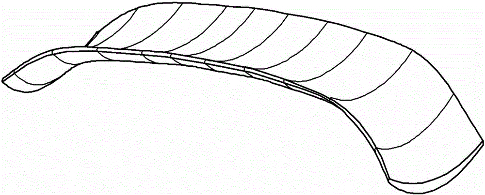
[0029] Step 1: Use 3D drawing software (UG software) to draw the 3D model of the blade body of the curved blade parts, such as image 3 shown;

[0030] Step 2: Execute the offset command in the 3D drawing software (UG software), set the offset amount according to the actual required machining allowance, and obtain the 3D model of the curved blade body after the allowance is increased, as shown in Figure 4 shown;

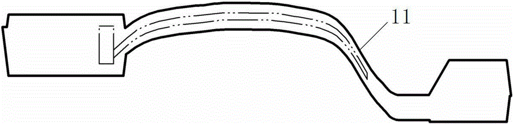
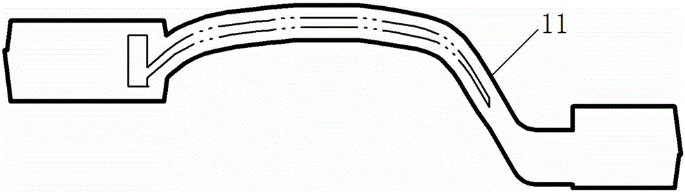
[0031] Step 3: According to the section distance of the drawing of the curved blade part, extract the part section line 1 and the forging section line 2 on the three-dimensional model of the curved blade part body after the margin is increased;

[0032] Step 4: Import the extracted part section line 1 and forging ...


PUM


Abstract

The invention provides a method for designing a blade body margin of an over-bent blade forge piece. The method comprises the following steps: drawing a three-dimensional model of a part blade body; executing an offset command according to machining margin to obtain a three-dimensional model of the part blade body with the margin increased; extracting section lines of the part and the forge piece according to a sectional distance on a part drawing; importing the section lines in two-dimensional drawing software; drawing two continuous inscribed circles on the exhaust edge of the section line of the part, and drawing an extension line of a connecting line of circle centers; drawing a normal of the extension line on a cross point of the extension line and the section line of the part; offsetting both sides of the extension line to obtain two symmetrical first offset lines, wherein the offset is a half of the thickness of a deckle edge of the exhaust edge of the section line at an over-bent site; offsetting a single side of the normal to obtain a second offset line, wherein the offset is the margin of the exhaust edge at the over-bent site, and the cross points of the first offset lines and the second offset line are respectively marked as first and second edge control points; moving two outer end points of the section line of the forge piece to the first and second edge control points; and inquiring all control points of the section line of the forge piece, and importing the same into a three-dimensional drawing software to generate a three-dimensional model of the blade body of the forge piece.

Description

technical field [0001] The invention belongs to the technical field of manufacturing aeroengine blades, and in particular relates to a method for designing blade body margins of curved blade forgings. Background technique [0002] With the continuous improvement of the thrust requirements of aero-engines, the blade shape of aero-engines also tends to be complicated. Taking a curved blade as an example, the line connecting the centers of gravity of each section of the curved blade body is close to the curve of the tip part. The curvature increases sharply, and the bending angle of the curved blade airfoil can reach up to 60°. If the traditional blade forging airfoil allowance design method is adopted, the following can be obtained: figure 1 For the blade forging shown, the local machining allowance at the bending part of the blade forging will be less than 30%, and the overall machining allowance distribution of the bending blade forging blade body is also very uneven, which ...

Claims


Application Information

Patent Timeline
Patent Type & Authority Applications(China)
IPC IPC(8): G06F17/50
CPCG06F30/15G06F30/17
Inventor 鞠秀义汪大成闫进军张广伟丁维
Owner SHENYANG LIMING AERO-ENGINE GROUP CORPORATION
Why Eureka
Try Eureka