
A Method for Optimizing Time Constant of Phase Compensation Link of Power System Stabilizer

A phase compensation and time constant technology, which is used in the field of suppressing low-frequency oscillation of the system and optimizing the time constant of the phase compensation link of the power system stabilizer, which can solve the problems of large workload, dependence, and no intelligent optimization model.

Active Publication Date: 2019-03-15
STATE GRID CORP OF CHINA +2
View PDF8 Cites 0 Cited by
  • Summary
  • Abstract
  • Description
  • Claims
  • Application Information

AI Technical Summary

Problems solved by technology

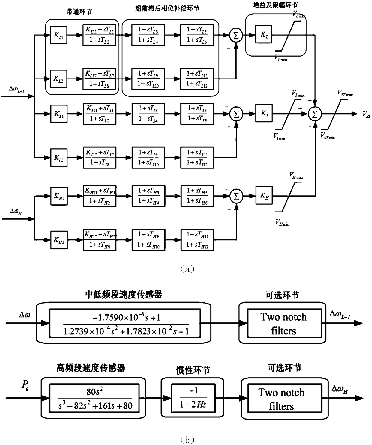
[0019] To sum up, at present, the parameter setting of PSS4B-W power system stabilizer is still in the stage of manual adjustment, the workload is heavy and depends on the experience of debugging personnel, and there is no intelligent optimization model suitable for PSS4B-W parameter setting

Method used


Image

  • A Method for Optimizing Time Constant of Phase Compensation Link of Power System Stabilizer
  • A Method for Optimizing Time Constant of Phase Compensation Link of Power System Stabilizer
  • A Method for Optimizing Time Constant of Phase Compensation Link of Power System Stabilizer

Examples


Embodiment 1

[0121] For the conventional self-shunt excitation system, a group of uncompensated phase-frequency characteristics are shown in Table 2. When the frequency is above 1.4Hz, the phase lag is greater than 90°.

[0122] Table 2 Non-compensated phase frequency characteristics of self-shunt excitation system

[0123]

[0124]

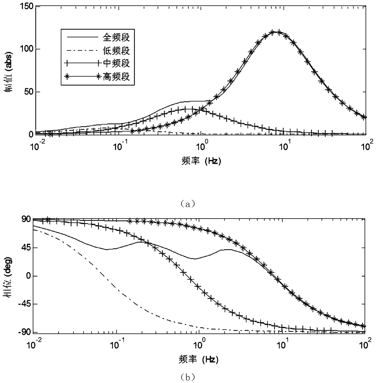
[0125] Use adaptive weighted particle swarm algorithm to optimize the parameters of PSS4B-W, and the optimized parameters are: T 1 = 0.209, T 2 = 6.126, T 3 = 5.653, T 4 =0.010, T 5 = 3.095, T 6 = 7.416. The corresponding PSS compensation phase frequency characteristics are as Image 6 It can be seen that the phase compensation effect of the optimized parameters of PSS4B-W meets the requirements of industry standards in the range of 0.1 to 2.0 Hz.

Embodiment 2

[0127] Table 3 shows a set of uncompensated phase frequency characteristics of the three-machine excitation system measured. It can be seen that its overall hysteresis characteristic is relatively large, with a lag of 150.09° at the local oscillation frequency of 1.9 Hz.

[0128] Table 3 Three-machine excitation system uncompensated phase frequency characteristics

[0129]

[0130] Use adaptive weighted particle swarm algorithm to optimize the parameters of PSS4B-W, and the optimized parameters are: T 1 =0.091, T 2 =0.010, T 3 = 0.137, T 4 =0.010, T 5 = 0.713, T 6 = 1.671. The corresponding PSS compensation phase frequency characteristics are as Figure 7 It can be seen that for the three-machine excitation system with large lagging phase frequency characteristics without compensation, the optimized parameters of PSS4B-W have a better compensation effect, and meet the requirements of industry standards in the range of 0.1 to 2.0 Hz.


PUM


Abstract

The invention discloses an optimization method of phase compensation link time constants of a power system stabilizer. The optimization method comprises the following steps of (1) measuring non-compensation phase-frequency characteristics of a unit excitation system by adopting a dynamic signal analyzer on the spot and reading a phase angle within a range of 0.1-2.0Hz; (2) converting the power system stabilizer into the PSS of a rotating speed deviation single-input mode according to structure characteristics of an electric power and rotating speed deviation double-input signal of a PSS4B-W; and (3) building a parameter optimization model of the PSS4B-W by employing third-order lead-lag phase compensation link time constants of the PSS4B-W as optimization variables and in-phase additional moment generated by the PSS and [delta]omega shaft as an optimization target and solving the time constants through an adaptive weight particle swarm optimization algorithm. According to the optimization method, optimized parameters, meeting the industry standard requirements, of the PSS4B-W can be quickly and efficiently found out.

Description

Technical field [0001] The invention relates to a method for optimizing the time constant of a phase compensation link of a power system stabilizer, which belongs to the field of power system stability and control, and is mainly used for suppressing low-frequency oscillation of the system. Background technique [0002] With the continuous expansion of the scale of power grids, the interconnection of large-scale power grids has become the development trend of modern power systems. The commissioning of long-distance and large-capacity transmission lines and fast, high-gain excitation systems has made low-frequency oscillation a key issue affecting the transmission capacity of interconnected power grids. Among the measures to suppress low-frequency oscillations, the power system stabilizer (PSS) has the advantages of clear concept, simple structure, and good effect, and has been widely used at home and abroad. Since the first PSS was put into industrial application in 1969, the mat...

Claims


Application Information

Patent Timeline
Patent Type & Authority Patents(China)
IPC IPC(8): H02J3/24
CPCH02J3/002H02J3/24H02J2203/20
Inventor 郭思源陈宏刘海峰洪权李振文蔡昱华吴晋波李大公李理
Owner STATE GRID CORP OF CHINA
Learn More