Motor drivers, servo drives and CNC machine tools

A motor driver and comparator technology, applied in the direction of control of electromechanical transmission, motor generator control, control of electromechanical brakes, etc., can solve the problems of low motor system response frequency band, low control signal frequency, large motor operating loss, etc., to achieve improved The effect of operating efficiency, improving the response frequency band, and strong dynamic anti-interference ability

Active Publication Date: 2019-05-10
SHANGHAI LYNAC NUMERICAL CONTROL TECH CO LTD
View PDF7 Cites 0 Cited by
  • Summary
  • Abstract
  • Description
  • Claims
  • Application Information

AI Technical Summary

Problems solved by technology

[0004] The technical problem to be solved by the present invention is to overcome the defects in the prior art that the frequency of the control signal output by the motor driver is very low, resulting in current deviation, large motor running loss and low motor system response frequency band, and to provide a A kind of motor driver, servo drive device and numerical control machine tool

Method used


Image

  • Motor drivers, servo drives and CNC machine tools
  • Motor drivers, servo drives and CNC machine tools
  • Motor drivers, servo drives and CNC machine tools

Examples


Embodiment Construction

[0032] The present invention is further illustrated below by means of examples, but the present invention is not limited to the scope of the examples.

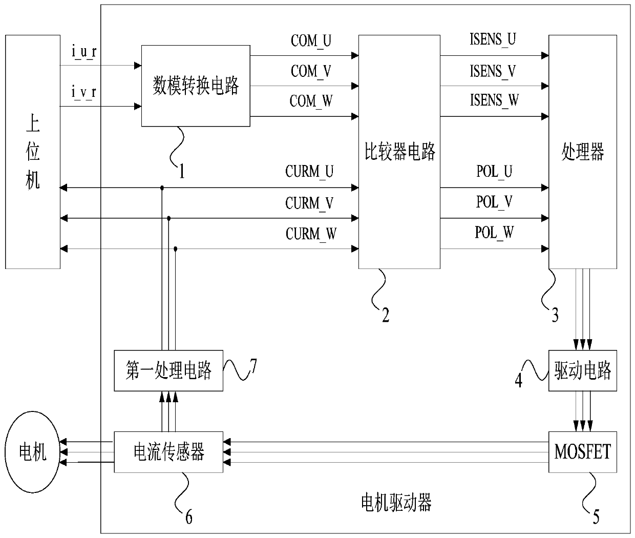
[0033] Such as figure 1 As shown, the motor driver of the present invention includes a digital-to-analog conversion circuit 1, a comparator circuit 2, a processor 3, a drive circuit 4, a MOSFET 5, a current sensor 6 and a first processing circuit 7 electrically connected in sequence;

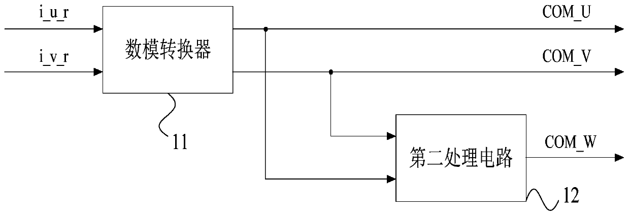
[0034] The digital-to-analog conversion circuit 1 is used to receive the U-phase command current digital signal (i_u_r) and the V-phase command current digital signal (i_v_r) sent by the external host computer and convert them into U-phase command current analog signals (COM_U) and V-phase A command current analog signal (COM_V), and generate a W-phase command current analog signal (COM_W) according to the U-phase command current analog signal (COM_U) and the V-phase command current analog signal (COM_V);

[0035] Such as figure 2 As shown, t...


PUM


Abstract

The invention discloses a motor driver, a servo drive device and a numerical control machine tool. The motor driver comprises a digital-to-analog conversion circuit, a comparator circuit, a processor, a driving circuit, a MOSFET and a first processing circuit, wherein the digital-to-analog conversion circuit, the comparator circuit, the processor, the driving circuit, the MOSFET, and the first processing circuit are sequentially and electrically connected together. The digital-to-analog conversion circuit receives a command sent from an external host computer, converts the instruction into a U-phase command current analog signal and a V-phase command current analog signal, and generates a W-phase command current analog signal. The comparator circuit compares the electric potentials of current analog signals and actual current signals with the ground potential, and sends a comparison result to the processor. The processor outputs a PWM control signal to the driving circuit. The driving circuit drives the MOSFET to output U-phase, V-phase and W-phase current signals to the first processing circuit. The first processing circuit generates an actual current signal. According to the technical scheme of the invention, the problems in the prior art, namely the low frequency of a PWM signal outputted by a conventional motor driver and the deviation condition of the current tracking thereof, can be solved.

Description

technical field [0001] The invention relates to the technical field of drivers, in particular to a motor driver, a servo driver and a numerically controlled machine tool. Background technique [0002] CNC machine tools are mainly composed of input / output devices, computer numerical control devices, servo drive devices and machine tool bodies. Motor drivers are one of the main components of servo drive devices, and their performance directly affects the performance of CNC machine tools. [0003] The frequency of the PWM (Pulse Width Modulation) control signal output by the motor drivers currently on the market is mostly in the range of 5KHz-10KHz, and the maximum does not exceed 20KHz. In the case of more precise current control requirements, the PWM frequency of 10KHz There will still be a large current deviation, and the command current given by the host computer cannot be perfectly reproduced, which will affect the control effect on the motor. Moreover, low PWM frequency ...

Claims


Application Information

Patent Timeline
Patent Type & Authority Patents(China)
IPC IPC(8): H02P21/00H02P21/14H02P21/22H02P25/02
CPCH02P21/14H02P25/02
Inventor 周兴鹏袁再松
Owner SHANGHAI LYNAC NUMERICAL CONTROL TECH CO LTD
Why Eureka
Try Eureka